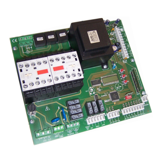
Allmatic CT3IND 설치 매뉴얼 - 페이지 3
{카테고리_이름} Allmatic CT3IND에 대한 설치 매뉴얼을 온라인으로 검색하거나 PDF를 다운로드하세요. Allmatic CT3IND 10 페이지. Programmable control board for sliding gates

2. Connections
T
1
S (N)
2
1
(L)
R
3
2
~ ~ ~
400 Vac
230 Vac
~
7
3
8
9
4
10
11
RED
12
13
5
GREEN
14
15
ALARM
16
20
6
18
20
7
19
COM.
21
8
S.S.
22
COM.
21
9
PED.
23
COM.
21
10
OPEN.
24
6-1622598
REV.3
23/09/2020
Connect the power supply cable between the
clamps 1, 2 and 3 of the control unit if a three-
phase power supply 400 Vac is used.
Connect the power supply cable between the
clamps 2 and 3 if a single phase power supply
230Vac is used.
POWER SUPPLY
Jumper the clamps 4 and 5 in case a 400
4
Vac three-phase power supply is used .
Jump the clamps
5 e 6 in case a single-
5
phase 230Vac power supply is used .
6
FLASHING LIGHT
Connect the flashing light between the clamps
COURTESY LIGHT
Connect the courtesy light between the clamps 9 and
10
TRAFFIC LIGHT
The outputs RED (11-12), GREEN (13-14) and
ALARM (15-16) are dry contacts (5A max) to
which a possible traffic light can be connected.
RED(11-12) and GREEN(13-14) are normally
open contacts (NO).
ALARM(15-16) is a normally closed contact
(NC).
IN2
This input plans the possibility to give a com-
mand of delayed closing to the automation.
IN1
This input plans the possibility to give an ope-
ning control to the automation.
STEP BY STEP INPUT
Connect the STEP-BY-STEP button (S.S.)
between the clamp 21 and 22 of the terminal
box.
ATTENTION: leave it open if not used.
PEDESTRIAN INPUT
Connect the PEDESTRIAN button (PED.)
between the clamp 21 and 23 of the terminal
box.
ATTENTION: leave it open if not used.
OPEN INPUT
Connect the OPEN button between the clamp
21 and 24 of the terminal box.
ATTENTION: leave it open if not used.
ITA
ENG
Do not connect the card directly to the electric
network. Put a device that can ensure the
disconnection of each pole from the power supply of
the control unit.
Attention: execute the jumper in a correct way. A
wrong cabling of the jumper could compromise the
correct functioning of the control unit.
Use a cable with adapt section according to the
absorbed current by the motor.
7 e 8
Use a flashing light without flashing circuit 230 Vac
60W max
Connecting a load 230Vac 100W MAX you can light
the operating area of the automation during each
movement. The functioning of the courtesy light is
controlled by a dedicated menu.
The traffic light outputs are activated in this way:
During the opening and closing movement the
output relay RED (11-12) is activated.
With the gate open the output relay GREEN (13-14)
is activated.
With the gate closed the outputs RED and GREEN
are disabled (open relay)
The output ALARM (15-16) is activated under the
condition of the control unit not enabled to the nor-
mal functioning (i.e.. stop activated, thermal, menu
activated)
It is possible to connect on this input, for example, a
magnetic loop that enables to give a closing pulse
to the automation. The input is excluded enabling
the functioning dead man. The counting of the time
of delay, starts from the release of the command
(opening of the contact)
It is possible to connect on this input, for example, a
magnetic loop that enables to give an opening pulse
to the automation. The input is excluded enabling
the functioning dead man.
Under the dead man mode, the step-by-step button
operates as open.
See function
Under the mode dead man the pedestrian button
operates as close.
See function
FRA
ESP
DEU
POR
3 / 10
