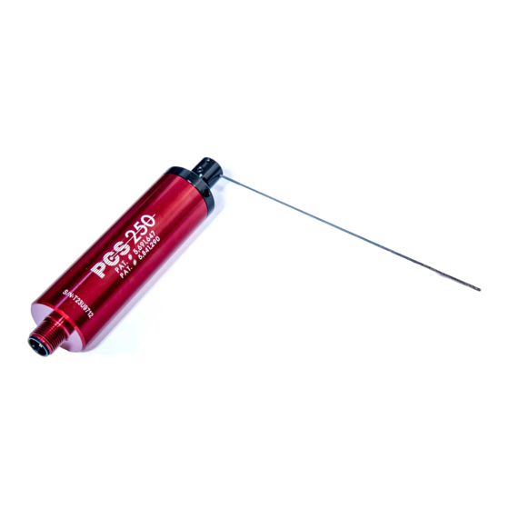
Allora Positive Contact PCS-250 설치 지침 매뉴얼 - 페이지 5
{카테고리_이름} Allora Positive Contact PCS-250에 대한 설치 지침 매뉴얼을 온라인으로 검색하거나 PDF를 다운로드하세요. Allora Positive Contact PCS-250 12 페이지.

Terminals 1 & 2: The TCU operates with 24VDC, note that terminal 1 is + and terminal 2
is - . This unit requires a minimum supply of 250 mA. When powering the TCU with an
existing 24VDC power supply, confirm that the supply is capable of additional output
capacity to power the TCU.
Terminal 3 . Is used as a remote Teach function. The required input is + 24VDC for a
minimum of 100mS. (OPTIONAL)
Terminals 4, 5, 6, 7 & 8: Sensor cable connection, as indicated. The preferred method
is to connect the cable directly from the sensor to the TCU. If the TCU and sensor need
to be connected via external junction box, avoid wiring near electromagnetic or high
current devices.
1
2 3 4 5
6
-
+
POWER
24VDC
OK
TEACH
FAULT
CCW
CW
1
NC
L
NC
L
2
TIME
ON
C&K SDA04
3
HI
LO
1
2
3
4
ET
NT
NO
M
NO
M
OK
START
FAULT
OUTPUT
OUTPUT
115V 24V
9
12
10
11
13
14
The start input can also be used as a RESET function. After the error condition has been
corrected ( replace broken tool ) applying a start signal will cause the sensor to begin the
scan sequence touching and confirming the tool has been replaced in-turn resetting the
fault condition on the control unit.
Certain solid state devices, although in their off ( LO ) state, may output a small amount
of current. Depending on the operating characteristics of these devices, the TCU may
not recognize a change of state. If this condition occurs in your application you may
need to incorporate an external relay to activate the checking sequence.
TCU Terminal Descriptions
DO NOT connect the braided shield in the supplied
sensor cable to the machine ground !
7 8
Terminals 9 & 10: are dry contacts ( internal relay ) capable
of switching 2A @ 250 VAC. The contact operation can be
configured eliminating peripheral devices for interfacing
the TCU (
Terminals 11 & 12: are dry contacts ( internal relay ) capable
of switching 2A @ 250 VAC. The contact operation can be
configured eliminating peripheral devices for interfacing the
see Relay Control Switches
TCU (
Terminal 13: Is used to reset the TCU after a fault condition
has been detected. The required input is + 24VDC for a
minimum of 100mS. (OPTIONAL)
Terminals 14, 15 & 16 are used to activate the
checking sequence when required in your application.
T-16 is the common for either a 115VAC start signal
(T-14 ) or a 24VDC start signal ( T-15 ). The TCU
recognizes a change of state in the circuit to activate
the checking sequence. A minimum duration of
15
16
100mS is required regardless of the of the signal
utilized, ( HI – LO – HI ) or ( LO – HI – LO ).
see Relay Control Switches
Page 4
, page 5)
, page 5)
