Miller 1038 운영자 매뉴얼 - 페이지 8
{카테고리_이름} Miller 1038에 대한 운영자 매뉴얼을 온라인으로 검색하거나 PDF를 다운로드하세요. Miller 1038 12 페이지. Fluid head
Operating Instructions
3
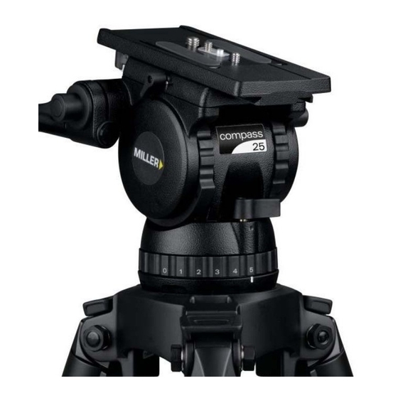
C o u n t e r b a l a n c e C o n t r o l
The counterbalance system was designed to neutralise the
effect of the camera weight when it is tilted. The Compass 25
Fluid Head offers a 4 position counterbalance system which
can be operated via the COUNTERBALANCE SELECTOR
(fig. 2). The COUNTERBALANCE SELECTOR must be
operated when the SLIDING PLATFORM is in a horizontal
position. After changing the Counterbalance setting it may be
necessary to tilt the camera back and forth to ensure that the
CB spring has engaged. The camera must be held securely
while changing the Counterbalance setting.
3.1 For safety ensure that Counterbalance position 4 is
selected.
3.2 Hold the camera and release the TILT LOCK, then gently
tilt the camera from a horizontal position forward then
backward and observe its response. If the Camera
'Springs Back' to the horizontal position then a lower
Counterbalance setting is required, select
Counterbalance position 3 and recheck, select lower
setting again if necessary. Correct counterbalance setting
has been achieved when minimum effort is required to
move the camera over the entire tilt range.
TIP Fine tuning can be achieved by adjusting the SLIDING
PLATFORM – see step 2.6.
Counterbalance Performance
Compass 25 Fluid Head Counterbalance.
300
250
200
150
100
50
0
0
2
4
6
8
8
10
12
14
16
18
20
22
24
26
Camera Payload (kg)
28
30