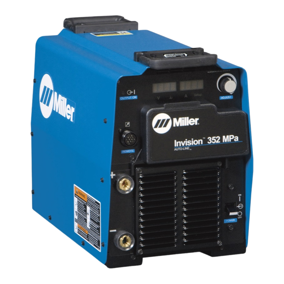
Miller Invision 352 MPa Auto-Line CE 소유자 매뉴얼 - 페이지 16
{카테고리_이름} Miller Invision 352 MPa Auto-Line CE에 대한 소유자 매뉴얼을 온라인으로 검색하거나 PDF를 다운로드하세요. Miller Invision 352 MPa Auto-Line CE 44 페이지.
Miller Invision 352 MPa Auto-Line CE에 대해서도 마찬가지입니다: 소유자 매뉴얼 (48 페이지), 소유자 매뉴얼 (44 페이지)

4-1. Features And Benefits
Auto-Linet Power Management Technology is circuitry that automatically adapts the power source to the primary voltage being applied
(see Sections 5-7 and 5-8).
LVCt Line Voltage Compensation is circuitry that keeps the power source output constant regardless of input power fluctuation.
Wind Tunnel Technologyt circulates air over components that require cooling, not over electronic circuitry, which reduces contaminants and im-
proves reliability in harsh welding environments.
Fan-On-Demandt cooling system operates only when needed, reducing noise, energy use and the amount of contaminants pulled through the ma-
chine.
Thermal Overload Protection automatically shuts down the unit, only when necessary to prevent damage to internal components if the duty cycle
is exceeded or air flow and cooling are restricted (see Section 4-9).
Auto Remote Sense enables the unit to automatically sense the connection of a remote control.
Synergic Pulsed MIG Operation With A Synergic Feeder allows single knob control of the arc. As wirefeed speed is increased or decreased, the
pulse parameters increase or decrease matching the power output to the wire speed.
4-2. Arc Controls
Inductance influences the arc stiffness, bead width and appearance, and puddle fluidity in MIG Welding Mode
(see Section 7-2).
SharpArct optimizes the size and shape of the arc cone, bead width and appearance, and puddle fluidity in Pulsed MIG Welding Mode (see Section
7-4).
4-3. Serial Number And Rating Label Location
The serial number and rating information for this product is located inside the case. Use rating label to determine input power requirements and/or
rated output. For future reference, write serial number in space provided on back cover of this manual.
4-4. Software Licensing Agreement
The End User License Agreement and any third-party notices and terms and conditions pertaining to third-party software can be found at
https://www.millerwelds.com/eula
4-5. Information About Default Weld Parameters And Settings
NOTICE − Each welding application is unique. Although certain Miller Electric products are designed to determine and default to certain typical welding
parameters and settings based upon specific and relatively limited application variables input by the end user, such default settings are for reference
purposes only; and final weld results can be affected by other variables and application-specific circumstances. The appropriateness of all parameters
and settings should be evaluated and modified by the end user as necessary based upon application-specific requirements. The end user is solely
responsible for selection and coordination of appropriate equipment, adoption or adjustment of default weld parameters and settings, and ultimate
quality and durability of all resultant welds. Miller Electric expressly disclaims any and all implied warranties including any implied warranty of fitness
for a particular purpose.
4-6. Unit Specifications
.
Do not use information in unit specifications table to determine electrical service requirements. See Sections 5-6 and 5-8 for information on con-
necting input power.
.
This equipment will deliver rated output at an ambient air temperature up to 1045F (405C).
Input
Power
Rated Output
3-Phase
350 A at 34
VDC, 60%
Duty Cycle
1-Phase
300 A at 32
VDC, 60%
Duty Cycle*
*See Section 4-9 for Duty Cycle Rating.
OM-246193 Page 12
.
A complete Parts List is available at www.MillerWelds.com
SECTION 4 − SPECIFICATIONS
and are incorporated by reference herein.
Amperage
Voltage
Range in
Range in CV Mode
CC Mode
10−38 V
5−425 A
RMS Amps Input at Rated Load Output,
Max.
60 Hz 3-Phase at NEMA Load Voltages
Open-
and Class I Rating
Circuit
208 V
230 V
400 V
Voltage
75 VDC
40.4
36.1
20.6
60.8
54.6
29.7
460 V
575 V
KVA
KW
17.8
14.1
14.2
13.6
25.4
19.9
11.7
11.2
