Chromalox RTPC 설치 지침 - 페이지 2
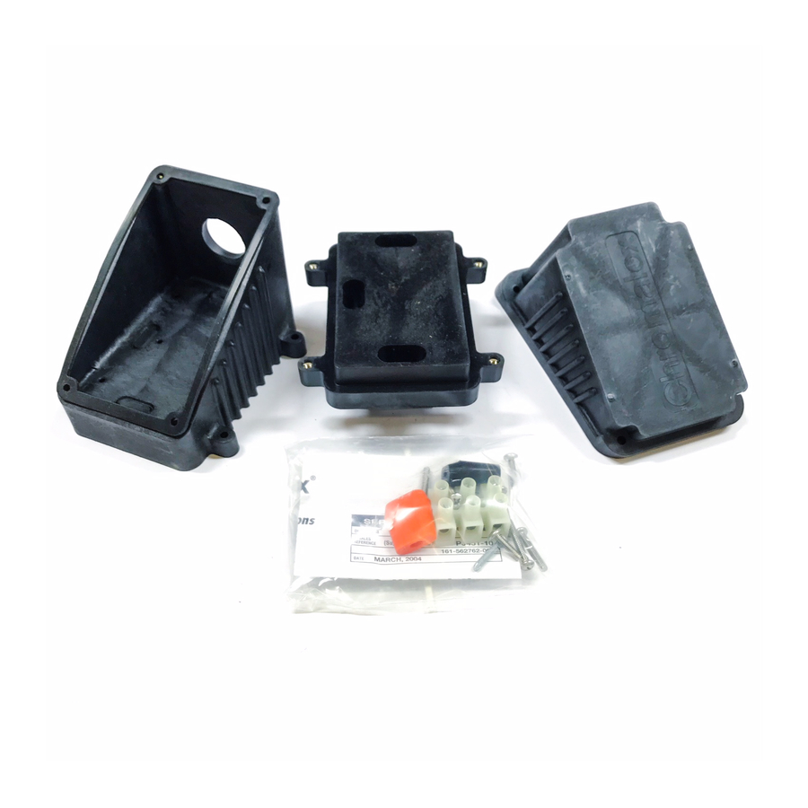
{카테고리_이름} Chromalox RTPC에 대한 설치 지침을 온라인으로 검색하거나 PDF를 다운로드하세요. Chromalox RTPC 4 페이지. Power connection kit for self-regulating & constant wattage heating cables
Chromalox RTPC에 대해서도 마찬가지입니다: 설치 지침 매뉴얼 (8 페이지)
NOTE: These instructions are for all Self-Regulating and
Constant Wattage heating cables in ordinary locations. Consult
factory for installation of braided cable in hazardous locations.
Not all instructions are for all cables. Each step of the instructions
will have a heading in boldface stating what type of cable each
instruction is intended for.
1. FOR CONSTANT WATTAGE CABLES:
Cut the cable 12 inches past the last module point (indentation
in cable). NOTE: Cutting the cable between module points
creates a non-heating cold lead. See Figure 1.
Module Point
2. FOR CABLE WITH EXPOSED METAL BRAID (-C):
Push the braid back 12 inches on the cable. See Figure 2.
3. FOR ALL CABLES:
Feed the ends of the cables through the appropriate hole in
the base. Allow eight (8) inches of cable to extend above the
top of the base. See Figure 3.
8"
4. FOR ALL CABLES:
Slide cable grommet over the end of the cable and insert it
into the opening in the base. Secure the base to the pipe by
threading the appropriate sized pipestrap through the slot in
the mounting plate. Tighten the pipestrap until the base is
securely attached to the pipe. See Figure 4.
INSTALLATION
12"
Figure 1
12"
Figure 2
Figure 3
5. FOR OVERCOATED CABLES (-CR or -CT):
Score the outer insulation seven (7) inches from the end of
cable. Remove the jacket to expose the metal braid. See Figure 5.
CAUTION: When removing the outer jacket, be
careful not to damage the braid or the base
cable insulation.
7"
6. FOR ALL CABLES:
Punch out the knockouts on the bottom of the box which cor-
respond to the openings in the base through which the heating
cable passes. Be careful to punch out only those knockouts to
be used. If one is mistakenly punched, blank grommets can be
ordered to re-establish the water tight seal. See Figure 6.
Figure 4
Figure 5
Figure 6