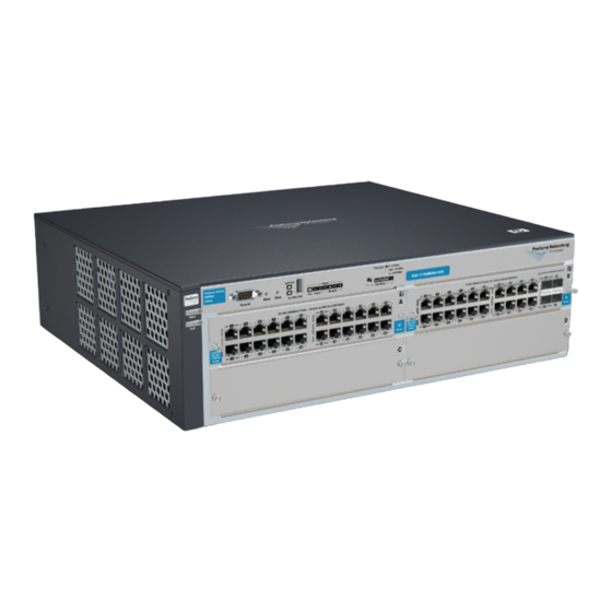
HP ProCurve 4208vl-72GS Bundle 설치 매뉴얼 - 페이지 2
{카테고리_이름} HP ProCurve 4208vl-72GS Bundle에 대한 설치 매뉴얼을 온라인으로 검색하거나 PDF를 다운로드하세요. HP ProCurve 4208vl-72GS Bundle 13 페이지. Hp procurve 4204vl: reference guide
HP ProCurve 4208vl-72GS Bundle에 대해서도 마찬가지입니다: 사양 (22 페이지), 데이터시트 (10 페이지), 빠른 참조 매뉴얼 (44 페이지)

9/18/2020
Ensure a cover plate is installed on any empty switch power supply slot. A cover plate is required for safe operation, and
to ensure proper switch cooling.
To avoid energy and mechanical hazards, never allow any partof body, jewelry, tool, or other foreign object to enter any
module or power supply slots.
Ensure that for any switch slot into which no module is installed, the cover plate is installed to cover the slot. A coverplate
is required for safe operation, and to ensure properswitch cooling. For safety, user should never have more thanone
module slot uncovered at a time while the switch is powered on.
CAUTION:
Ensure the power source circuits are properly grounded, then use thepower cord supplied with the switch to connect it to
the power source. If installation requires a different power cord than the one supplied with the switch and power supply, be
sure the cord is adequately sized for the switch's current requirements. In addition, be sure to use a powercord displaying
the mark of the safety agency that defines the regulations for power cords in user's country. The mark is an assurance that
thepower cord can be used safely with the switch and power supply.
When installing the switch, note that the AC outlet should be near the switch and should be easily accessible in case the
switch must bepowered off.
Ensure the switch does not overload the power circuits, wiring, and over current protection. To determine the possibility of
overloading the supply circuits, add together the ampere ratings of all devices installed on the same circuit as the switch
and compare the total with the rating limit for the circuit. The maximum ampere ratings are usually printed on the devices
near the AC power connectors.
Do not install the switch in an environment where the operating ambienttemperature might exceed 40°C (104°F).
Allow three to four inches of space around the sides and back of theswitch to make sure the air flow for the switch is not
restricted.
top
Prepare the installation site
Cabling Infrastructure: Ensure the cabling infrastructure meets the necessary network specifications. See the following table for cable
types and lengths.
Port Type
Cable Type
Twisted-pair cables
10/100/1000Base-
For either 10, 100 Mb/s or 1000 Mbpsoperation:Category 5 or better, 100-ohm UTP or shielded
T
Twisted-pair (STP) balanced cable. For 1000 Mbps (Gigabit) operation, Category 5e cabling or
better is recommended.
Fiber optic cables
Gigabit-SX(On
Multimode fiber-optic cables fitted with LC connectors
Gigabit-SX-
LCmini-GBIC)
Gigabit-LX (On
Single-mode fiber-optic cables fitted with LC connectors.
Gigabit-LX-
The multimode cables specified for the Gigabit-SX mini-GBIC may also be used, but a mode
LCmini-GBIC)
conditioningpatch cord may be needed.
Gigabit-LH (On
Single-mode fiber-optic cables designed forGigabit Ethernet and fitted with LC connectors.
Gigabit-LH-
LCmini-GBIC)
NOTE:
Gigabit-LH - The transmission distances are dependent on the particular fiber loss and coupling loss involved, among other factors, and can be estimated from the
optical loss budget. For distances less than 20 km, a 10 dB attenuator must be used. For distances between 20 km and 40 km, a 5dB attenuator must be used. Attenuator
can be purchased from most cable vendors.
10 GbE SR
Multimode fiber-optic cable designed forGigabit Ethernet: 62.5/125 μm (Core/cladding) diameter
or 50/125 μm, low metal content,complying with the ITU-T G.652 and ISO/IEC793-2 Type B1
standards.
10 GbE LR
9/125 μm (Core/cladding) diameter, low metalcontent, single mode fiber-optic cables,complying
with the ITU-T G.652 and ISO/IEC793-2 Type B1 standards.
10 GbE ER
9/125 μm (Core/cladding) diameter, low metalcontent, single mode fiber-optic cables,complying
with the ITU-T G.652 and ISO/IEC793-2 Type B1 standards.
CX4
12 Fiber 50/125 μm (Core/cladding) diameter,multimode Fiber ribbon cable. 12 fiber 62.5/125μm
MediaConverter
(Core/cladding) diameter, multimode Fiberribbon cable is also supported.
HPE 4200 vl Switch Series - Installation
Length Limits
1
100 m
The Auto MDI/MDI-X feature only works when the
port is in auto-negotiation mode.
62.5 μm cable
160 MHz/km = 220 m
200 MHz/km = 275 m
50 μm cable
400 MHz/km = 500 m
500 MHz/km = 550 m
Single-mode cable = 10 km
Multimode cable = 550 m
Single-mode cable = 70 km
62.5 μm cable:
160 Mhz/km = 2 - 26 m
200 Mhz/km = 2 - 33 m
50 μm cable:
400 Mhz/km = 2 - 66 m
500 Mhz/km = 2-82 m
2000 Mhz/km = 2 - 300 m
Single-mode cable: 2 - 10 km
Single-mode cable: 2 - 30 km (40 km, on an
engineered fiber optic linkthat meets standards in
the specification).
50 μm cable or 62.5 μm cable: 100 m
2/12
