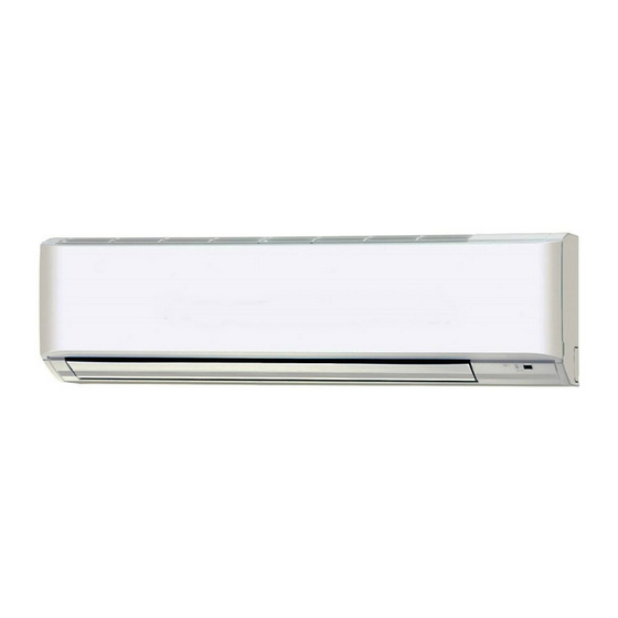
Panasonic U-20ME1E81 설치 지침 매뉴얼 - 페이지 18
{카테고리_이름} Panasonic U-20ME1E81에 대한 설치 지침 매뉴얼을 온라인으로 검색하거나 PDF를 다운로드하세요. Panasonic U-20ME1E81 25 페이지. Wall mounted (k1 type),
mini vrf (le1 type),
2way vrf (me1 type),
3way vrf (me2 type)
Panasonic U-20ME1E81에 대해서도 마찬가지입니다: 빠른 참조 매뉴얼 (24 페이지), 사용 설명서 (26 페이지), 사용 설명서 (25 페이지), 설치 매뉴얼 (9 페이지), 설치 지침 매뉴얼 (28 페이지), 사용 설명서 (10 페이지)

How to connect wiring to the terminal
■ For stranded wiring
(1) Cut the wire end with cutting pliers,
then strip the insulation to expose
the stranded wiring about 10 mm and
tightly twist the wire ends. (Fig. 4-7)
(2) Using a Phillips head screwdriver,
remove the terminal screw(s) on the
terminal plate.
(3) Using a ring connector fastener or
pliers, securely clamp each stripped
wire end with a ring pressure terminal.
(4) Place the ring pressure terminal,
and replace and tighten the removed
terminal screw using a screwdriver.
(Fig. 4-8)
■ Examples of shield wires
(1) Remove cable coat not to scratch braided shield. (Fig. 4-9)
(2) Unbraid the braided shield carefully and twist the
unbraided shield wires tightly together. Insulate the shield
wires by covering them with an insulation tube or wrapping
insulation tape around them. (Fig. 4-10)
(3) Remove coat of signal wire. (Fig. 4-11)
(4) Attach ring pressure terminals to the signal wires and the
shield wires insulated in Step (2). (Fig. 4-12)
■ Wiring sample
F2 type
Protective ground screw
(External Solenoid Valve Kit for 3WAY)
Stranded wire
Ring
pressure
terminal
Use this screw when connecting the shield
for the Inter-unit control wiring to ground.
Special
washer
Wire
Fig. 4-7
Functional ground screw
(External Electronic Expansion Valve Kit and Schedule Timer)
18
Screw
Ring pressure
terminal
Terminal plate
Wire
Fig. 4-8
Fig. 4-9
Insulation tape
Shield mesh
Fig. 4-10
Insulation tape
Shield mesh
Fig. 4-11
Fig. 4-12
Remote Control
Wiring
Power Supply
Screw and
Special washer
Ring
pressure
terminal
Inter-unit Control
Wiring
