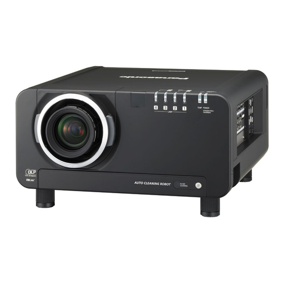
Panasonic PT-DW10000 조정 매뉴얼 - 페이지 10
{카테고리_이름} Panasonic PT-DW10000에 대한 조정 매뉴얼을 온라인으로 검색하거나 PDF를 다운로드하세요. Panasonic PT-DW10000 17 페이지. 3-chip dlp projector
Panasonic PT-DW10000에 대해서도 마찬가지입니다: 사양 시트 (10 페이지), 사양 시트 (10 페이지), 사양 (12 페이지), 치수 (1 페이지), 치수 (1 페이지), 설정 및 운영 매뉴얼 (37 페이지), 사양 (11 페이지), 브로셔 및 사양 (6 페이지)

(3) Considerations for the System Design of the Signal Delivery System
1) Enter the same signal into each projector
The projector input signal for edge blending needs to be equalized using a distributor
Adjustment data for each input signal needs to be registered in the projector memory.
2) When projecting individual images in addition to edge-blended images
When registering individual images in the memory, create a sub-memory, and adjust the
image to a smaller size to avoid image overlapping. (3-chip DLP type: Max. 96 memories,
1-chip DLP type: Max. 8 memories). At this time, the image size can be made greater without
changing the aspect ratio by moving the image contour position with the help of the raster
position function. Raster position adjustment, therefore, needs to be made in order to avoid
image overlapping.
3) Considerations when unifying multiple input signals into a unified frequency using a
scan converter
When multiple units of personal computers are connected to a single set of projectors, even
the same XGA signal is slightly different for each PC in terms of the signal level, phase,
displayed area etc, and edge blending needs to be adjusted every time the PC is changed.
A scan converter unifies multiple output signals into a single type and the amount of
registration into the projector memory is much reduced.
Considerations for setting up a multi-scan converter
Setting up an output resolution of a multi-scan converter according to the DMD resolution of
the projector
Example: D7700 (1400 dots x 1050 dots)
Unifying the output signal level, image enlargement rate, image shift etc of a multiple
number of multi-scan converters
Default output setting is desirable.
Slight variation exists in the dot clock and phase of each multi-scan converter.
For each pair of a projector and multi-scan converter, the dot clock of the projector needs to
be adjusted.
In this case, the dot clock of the projector is adjusted by delivering the internal test pattern of
the multi-scan converter. Connection with DVI cable is recommended.
Photo 6
Photo 6 shows the condition of out-of-dot
clock in the projector on the left-hand
side.
An out-of-dot clock condition with a
multi-scan converter even makes the hue
and brightness change.
- 10 -
