Biomorph Pro SuperPlus 매뉴얼 - 페이지 13
{카테고리_이름} Biomorph Pro SuperPlus에 대한 매뉴얼을 온라인으로 검색하거나 PDF를 다운로드하세요. Biomorph Pro SuperPlus 15 페이지.
Biomorph Pro SuperPlus에 대해서도 마찬가지입니다: 매뉴얼 (15 페이지)
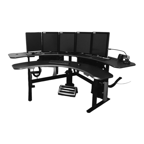
Cable Diagram
IMPORTANT:
All cables must be tacked up and made neat with supplied cable guides. NO cables may hang down ex-
cept those passing through cable chains. Make sure cables have enough slack between surfaces to allow
full height adjustment between surfaces.
IMPORTANT:
Extend desktops to full opposite heights to ensure that cables will travel w/o stress).
CABLE CHAIN
Use to run cables from front surface
to rear surface. Push in from inside.
CABLE CAB
(Optional) Place door towards user.
3 PORT CONTROLLER
box for REAR surface
LONG CABLE/
FRONT LEG
POWER CABLE
SHORT CABLES
Use SHORT cables to connect 3 rear legs
to ports #1, #2 & #3 in controller box.
POWER CABLE
Connect power cables to power
strips inside cable cabs.
SWITCH
for REAR surface use long 45˚ angle bracket.
Control switches connect to port A1.
LONG CABLES
Use LONG cables to connect both front
legs to ports #1 & #2 in controller box.
2 PORT CONTROLLER
box for FRONT surface
LONG CABLE/
FRONT LEG
POWER CABLE
SWITCH
LONG CABLE/FRONT LEG
SHORT CABLE/REAR LEG
SHORT CABLE/REAR LEG
CABLE TRACKS
SWITCH
LONG CABLE/
SWITCH
FRONT LEG
for FRONT surface use long 45˚ angle bracket.
Control switches connect to port A1.
12
GROMMET HOLE
Place grommet into
grommet hole. Route
cable accordingly.
q
WIRE CLIP
A wire clip MUST be placed directly
behind switch to prevent cable droop