EPC EPC9084 빠른 시작 매뉴얼 - 페이지 3
{카테고리_이름} EPC EPC9084에 대한 빠른 시작 매뉴얼을 온라인으로 검색하거나 PDF를 다운로드하세요. EPC EPC9084 7 페이지. 350 v half-bridge with gate drive, using epc2050
QUICK START GUIDE
EPC – EFFICIENT POWER CONVERSION CORPORATION |
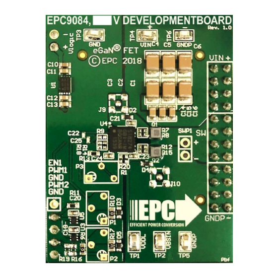
EPC9084
Gate drive
V
DD
regulator
Logic and
PWM
dead-time
adjust
GND
Figure 2: Block diagram of EPC9084 development board
7.5 – 12 V
DC
+
V
supply
IN
(note polarity)
Q1 Gate
(HIGH VOLTAGE!)
Dead-time Adjust
(Single PWM)
Dead-time Adjust
(Dual PWM)
Enable
Control
Signal
Inputs
Figure 3: Proper connection and measurement setup
V
= 40 V/div
DS
V
= 2 V/div
GSQ2
V
= 280, V
IN
Figure 4: Typical Waveform for the EPC9084 operating as a buck converter
WWW.EPC-CO.COM
LDO
Gate driver (Si8274)
Main Voltage Measurement
>
(HIGH VOLTAGE)
= 28 V, I
= 4 A, f
= 50 kHz, L
OUT
OUT
SW
| COPYRIGHT 2018 |
V
IN
Q
Output
1
L
Buck
DC Output
C
C
Bypass
Q
2
PGND
Switch-node
oscilloscope probe
280 V
DCmax
+
Output
Ground
V
supply
oscilloscope probe
Main
(note polarity)
G2 Gate
5 V control supply voltage
DC Control supply Voltage
Ground
10 ns/div
= 440 H
Buck
EPC9084
OUT
| 3