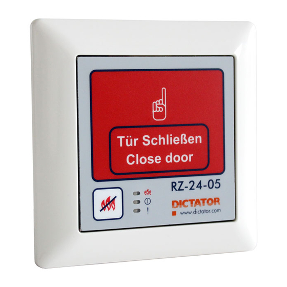
Dictator RZ-24-05 Central 기술 매뉴얼 - 페이지 11
{카테고리_이름} Dictator RZ-24-05 Central에 대한 기술 매뉴얼을 온라인으로 검색하거나 PDF를 다운로드하세요. Dictator RZ-24-05 Central 12 페이지.
Dictator RZ-24-05 Central에 대해서도 마찬가지입니다: 기술 매뉴얼 (13 페이지)

7a) Functions of the
RZ-24-05
© DICTATOR Technik GmbH • Gutenbergstr. 9 • 86356 Neusäß • Germany
Tel. +49(0)821-24673-0 • Fax +49(0)821-24673-90 • E-mail [email protected] • 20200513
7. Functioning/Adjusting Instructions of the RZ-24-05
- RESETTING the complete hold-
open system after an alarm:
Firstly reset the fire detectors by means
of the hand release key (1) on the
cover of the casing. For this purpose
press the key longer than 3 s. Now the
entire system can be switched back into
operation with the RESET button (2) of
the central.
LED indicator "Trip"
The "Trip" LED indicator lights up red when the RZ-24-05 detector loop
is tripped. The "electromagnet" output is switched off, the "warning
light" output is switched on.
LED indicator "Ready"
The "ready" LED indicator lights up green when the RZ-24-05 detector
loop is ready (not triggered). The "electromagnet" output is switched
on, the "warning light" output is switched off.
LED indicator "Error"
The "Error" LED indicator lights up or flashes yellow. A permanently
yellow LED indicates a serious defect of the RZ-24-05. A yellow flashing
LED indicates various other errors: The individual errors are indicated
by the flashing LED one after the other. The messages are separated by
a pause of 1 second (LED off).
1 x flashing = undervoltage error, i.e. the operating voltage has dropped
below 15 V.
2 x flashing = flash memory error of the controller.
3 x flashing = output electromagnet overload or open.
A short flash of the LED "Error" when switching on the controller is normal
and serves to test the display.
Example: Undervoltage error and flash memory error are pending:
1 x yellow flashing, pause 1 s, 2 x yellow flashing, pause 1 s, 1 x yellow
flashing, pause 1 s and so on.
Technical Manual
RZ-24-05 Central
(1)
(1)
(2)
(3)
Page 07.021.11
Ill. 6
