EPH Controls RFC 운영 지침
{카테고리_이름} EPH Controls RFC에 대한 운영 지침을 온라인으로 검색하거나 PDF를 다운로드하세요. EPH Controls RFC 2 페이지. Rf cylinder thermostat
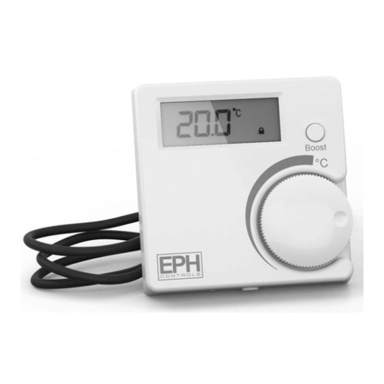
RFC - RF Cylinder Thermostat
Contents
1.
Factory default settings
2.
Speci cation & wiring
3.
Mounting
4.
Installation
5.
Button / symbol description
6.
Resetting the thermostat
7.
Boost function
8.
Lock function
9.
To connect the RFC thermostat to the
R_7-RF programmer
10. To disconnect the RFC thermostat from
the R_7-RF programmer
Important: Keep this document
Prior to setting the thermostat, it is neccessary to complete all required settings described
in this section.
1. Factory default settings
Temperature indicator:
Switching di erential:
In built frost protection:
Keypad lock:
2. Speci cations & wiring
Power Supply:
Power consumption:
Battery replacement:
Temp. Control Range:
Dimensions:
Temp. sensor:
Temp. indication:
3a Mounting of temperature sensor
ON CYLINDER: To ensure accurate control of your cylinder, the temperature
sensor should be mounted on the bottom 1/3 of the cylinder. It is essential that
the sensing element is in direct contact with the cylinder and that there is no
insulation between it and the cylinder. 60°C is the temperature level required in
order to prevent the build up of legionella bacteria. The temperature sensor can
be xed to the cylinder using the provided foil tape.
ON PIPEWORK: To ensure accurate control, the temperature sensor should be
mounted on the pipework as tightly as possible. It is essential that the sensing
element is in direct contact with the pipework and that there is no insulation
between it and the pipework. The temperature sensor can be xed to the
pipework using the provided foil tape.
3b Mounting of thermostat
The thermostat should be mounted in a position that will make reading
the display conventient.
The thermostat can be tted to: 1. Recessed conduit boxes
4. Installation
Press the button on the bottom of the thermostat.
The front housing will detach from the baseplate.
Insert the batteries (provided) into the thermostat.
Mount the unit as described in section 3. Ensure the cable sensor is
connected to terminals Con 3 and Con 4.
O er the baseplate up to the thermostat. Snap it into position to close.
°C
2.5°C
5°C
O
2 x AAA Alkaline Battery
50 uA
Once per year
10...90°C
84 * 84 * 30mm
NTC 10K Ohm @ 25°C - 1.5m probe type
°C
2. Surface mounting boxes
3. Directly on walls
EPH Controls Ireland
Sitecast Industrial Estate, Pouladu ,
Cork, T12 W665, Ireland
[email protected] www.ephcontrols.com
Page 1 of 2
Operating Instructions
Only quali ed electricians or authorised
service sta are permitted to open the
thermostat.
Ensure that this wireless enabled
thermostat is installed 1 metre from any
metalic object, television, radio or wireless
internet transmitter.
5. Button / symbol description
Heating ON symbol
Water temperature
Reset button
6. Resetting the thermostat
Press the
button on the bottom of the thermostat, the front housing
will detach from the baseplate.
Insert the batteries into the thermostat.
Press the reset button on the PCB, 'NO' will ash on the screen.
Rotate the hand wheel clockwise until 'YES' appears on the screen.
Press the hand wheel once to con rm the setting.
The thermostat has now been reset and the current temperature will
appear on the screen.
7. Boost function
Press the boost button once, twice or three times to boost the heating for
1, 2 or 3 hours respectively. +1H, +2H or +3H will appear on the screen.
The boost function will override the programmer if the programmer is
timed to be O .
8. Lock function
To lock the thermostat, press the hand wheel for 10 seconds. The keypad
symbol will appear on the screen.
To unlock the thermostat, press the hand wheel for 10 seconds. The
keypad symbol will disappear from the screen.
EPH Controls UK
Unit E4, Welland Business Park, Valley Way, Market Harborough,
Leicestershire, LE16 7PS, United Kingdom
[email protected] www.ephcontrols.co.uk
CAUTION!
Wireless symbol
Battery low symbol
Boost button
Set point handwheel
Code button