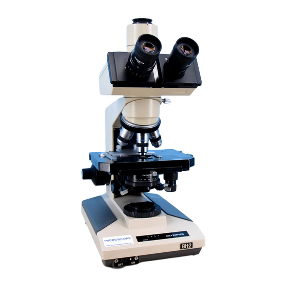
Olympus B2-BDS-3 문제 해결 및 조정 매뉴얼 - 페이지 38
{카테고리_이름} Olympus B2-BDS-3에 대한 문제 해결 및 조정 매뉴얼을 온라인으로 검색하거나 PDF를 다운로드하세요. Olympus B2-BDS-3 46 페이지. For electrical base

D.
TROUBLESHOOTING (B2-BDS-3)
No. D-7
@
Is
the
input voltage
of the
display PCB Ul03
normal?
@)
NO
() YES
t
Is the
input
voltage
of the
secondary PCB
Ul02
normal?
NO
t
YES
)-----t~-®
Replace the
Ul02.
®
'
Proceed
the
work
according
~I
Replace
the
Ul03
@
Measure
the input
voltage of the
display PCB
Ul03 with a multimeter.
Normal if the input
voltage is as
specified in the
following table
when the light intensity
control
lever is moved
from "Min" to "Max".
Abnormal if not.
Input
voltage
CNlii] blue
- CNl
m
purple
Approx. DC17-
CNl
[1]
gray - CNl
m
purple
l4V
to "No.
J-
4. Power Supply"
CN2@] gray - CN2
m
Approx. DC2.5- l2V
*
~
Measure the input
voltage of the
secondary PCB Ul02
with a
multimeter.
Normal if the input
voltage is as
specified in the
following table when
the light intensity
control lever
is
moved from
"Min"
to "Max".
Abnormal
if not.
Input voltage
Ul02lH-ll gray - Ul02Jw-llwhite
Approx. ACS- 20V
CN3
[]J
black
- CN3
[}) white
Approx. AC4V
CN2
IIJ
purple - CN2
IT]
Approx. DC14
-
l7V
CN2
[1]
blue
- CN2
m
Approx. DC14
-
l7V
*
Approximately
ACO.BV is detected
when the
light
intensity
control
lever is set to the "Min"
position
and the
main switch is
turned
on.
This is not defective.
When the
light intensity
control lever is
moved toward the
"Max" direction
after the main switch is turned
on
and the voltage
once reaches ACSV,
the voltage is
not
lowered
even if
the lever is
moved back to the "min"
position.
"Approx. ACS -20V" in
the
table indicates
this state.
