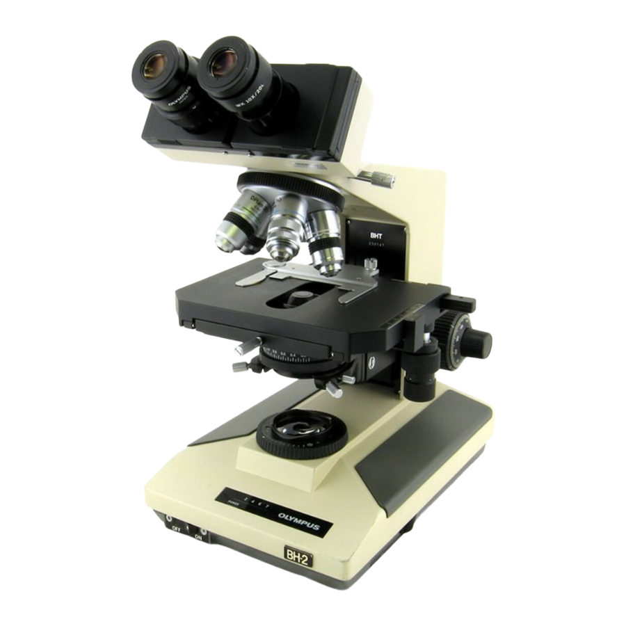
Olympus BH2 Series 완전한 분해, 청소 및 재조립 - 페이지 24
{카테고리_이름} Olympus BH2 Series에 대한 완전한 분해, 청소 및 재조립을 온라인으로 검색하거나 PDF를 다운로드하세요. Olympus BH2 Series 40 페이지. Phase contrast
Olympus BH2 Series에 대해서도 마찬가지입니다: 문제 해결 및 조정 매뉴얼 (46 페이지), 완전한 분해, 청소 및 재조립 (23 페이지), 분해, 청소 및 재조립 (45 페이지), 매뉴얼 (6 페이지), 설치 매뉴얼 (9 페이지)

wave washer, with the greased surface contacting the
metal wave washer (see
Figure 69 – Reinstall the greased nylon tension washer
Apply a light coating of grease onto the threads of the
brass pinion mount and loosely thread the tension-
adjustment knob onto the brass pinion mount (see
Figure
70) from behind the gear. Note that these parts
have left-handed threads.
Figure 70 – Reinstall the tension-adjustment knob
Snug the tension-adjustment knob onto the brass
pinion mount, making sure that the index screw on the
brass pinion mount seats into the notch in the nylon
tension washer as the tension-adjustment knob is
snugged down (see
Figure
tension-adjustment knob.
Figure 71 – Snug the tension-adjustment knob
Complete Teardown, Cleaning, and Reassembly of the Olympus BH-2 Coaxial Focus Mechanism
Figure
69).
71). Do not fully tighten the
Reinstall the Pinion Assembly into the Pillar Arm
From the right-hand side of the pillar arm, carefully
insert the pinion assembly, with the tension-adjustment
knob and the two tension washers installed, into the
bore of the pillar arm casting (see
insert the pinion assembly into the pillar arm casting in
the proper orientation such that the two indexing holes
drilled into the brass pinion mount (see
align with the two tapped setscrew holes in the pillar
arm casting (see
Figure
Figure 72 – Slide the pinion assembly into the pillar arm
Use a flashlight to peer into the two tapped setscrew
holes in the pillar arm casting (see
position the pinion mount such that the two indexing
holes (see
Figure
73) can be seen through the tapped
holes. This is the proper orientation for the installation
of the setscrews, since they are designed to bite into
the indexing holes in the pinion mount when they are
tightened down, thereby holding the pinion assembly in
the correct position and orientation within the bore of
the pillar arm casting.
Figure 73 – A view of the indexing holes in the pinion mount
Use a 1.5mm Allen tool or driver to start the two M3X5
setscrews into the tapped holes in the pillar arm casting
Figure
72). Be sure to
Figure
72).
Figure
Revision 4
Page 24 of 40
73) will
72) and
