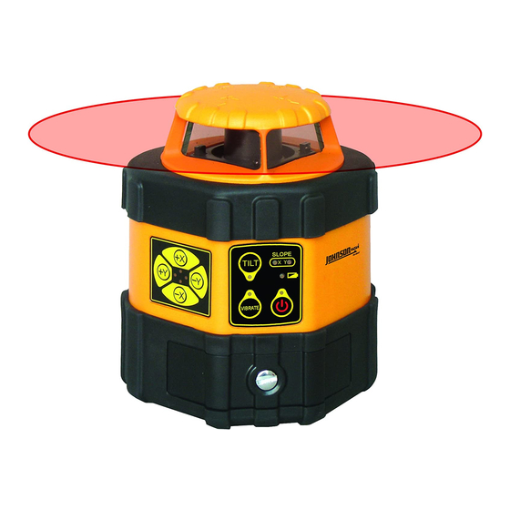
AccuLine 40-6537 서비스 매뉴얼 - 페이지 14
{카테고리_이름} AccuLine 40-6537에 대한 서비스 매뉴얼을 온라인으로 검색하거나 PDF를 다운로드하세요. AccuLine 40-6537 15 페이지. Auto-leveling rotating laser
AccuLine 40-6537에 대해서도 마찬가지입니다: 사용 설명서 (18 페이지)

3.2. Vertical Mode Operation
In this mode of operation, the rotating laser surface is a plumb plane, while the laser line projected from the top is in projecting
horizontal. While in this mode, the instrument is manually level, meaning that accuracy is a function of how accurately the vial
is calibrated. The 40-6537 is not designed for Vertical Mode Operation.
3.3. Alarm Calibration
The alarm function is made up of 3 components, the 2 alarm PCB's (7-15-17, 7-14-13) and the buzzer (10-3). Calibrating it is a
matter of centering the contact ring of 7-14-13 to the spring post of 7-15-17. When the spring post makes contact with the
contact ring of 7-14-13, the buzzer (10-3) sounds. Centering the post between the ring offers equal angular alarming in all
directions. Adjustments are made as follows:
a.
Remove the Upper housing assembly as shown in section 2.1.
b.
Locate the adjustment screws 6-10 (reference section 2.3).
c.
Loosen the adjustment screws 6-11and 6-12 to manually center
the contact ring to the spring post.
d.
Tighten the adjustment screws and reassemble the upper
housing assembly to the base assembly.
4.0. Electrical Connections
4#
X
8#
Prepared By: Tim Wojo
1#
FFC 连接线
Y
PO W
9#
10#
Revision - Date: 0 – 03232009
8# alarm circuit board part
2#
FFC 连接线
5#
11#
FFC 连接线
6#
X传感器
Y传感器
40-6537 Service Manual
Adjustment screw (2pcs)
3#
12#
Page 14 of 15
