Olympus BH-NRE 매뉴얼 - 페이지 12
{카테고리_이름} Olympus BH-NRE에 대한 매뉴얼을 온라인으로 검색하거나 PDF를 다운로드하세요. Olympus BH-NRE 17 페이지. Modular revolving nosepiece
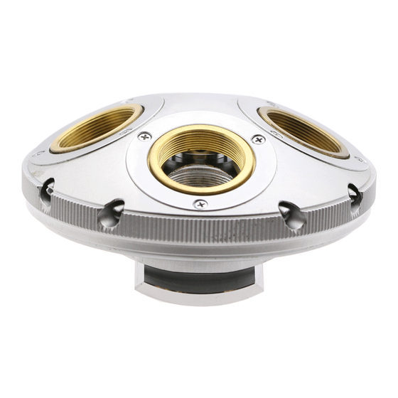
Figure 33 – Reinstall the slotted lock ring
Spin the revolving turret until one of the four threaded
objective bores in the revolving turret aligns with the
bore in the stationary base. Insert a suitably sized
screwdriver handle into these bores to lock the
revolving turret to the stationary base. Use a suitable
tool (see
Figure
11) to snug the slotted lock ring down
to lock the pivot-adjustment screw in place (see
34). Do not allow the pivot-adjustment screw to rotate
while tightening the slotted lock ring.
screwdriver from the bores after the slotted lock ring
has been tightened.
Figure 34 – Tighten the slotted lock ring
Verify the Feel of the Revolving Nosepiece
Hold the turret assembly by gripping the stationary base
in one hand and spin the revolving turret with the other
hand. The motion of the turret should not feel gritty,
erratic, or excessively stiff. If it does feel gritty or stiff,
loosen the slotted lock ring, readjust the pivot-
adjustment screw, and retighten the slotted lock ring as
described above until the turret motion feels
acceptable.
Clean Off Any Visible Grease
Use a suitable solvent (e.g., mineral spirits) and a clean
rag or tissue to thoroughly clean any visible grease from
the exterior of the turret assembly. Be careful while
removing the excess grease to prevent any of the
Complete Teardown, Cleaning, and Reassembly of the Olympus BH-NRE Modular Revolving Nosepiece
solvent from dripping into the revolving turret
mechanism and fouling the grease within.
Reinstall the Mechanical Detent Stop
Place the mechanical detent stop in position on the
stationary base, aligning the two holes in the
mechanical detent stop plate with the two tapped holes
in the stationary base (see
positioning the mechanical detent stop, make sure that
you orient it such that the detent ball (which is
cemented to the mechanical detent stop plate) is facing
downwards, towards the stationary base, so that it will
engage with the V-notches in the base as the revolving
turret is turned.
Figure
Remove the
Figure 35 – Place the mechanical detent stop in position
Use a suitable JIS screwdriver to reinstall two M2X4
pan-head screws to secure the mechanical detent stop
into place on the stationary base, with the detent ball
facing downwards (see
Reinstall the Dovetail Slide
Place the dovetail slide into position on the back side of
the turret assembly, lining up the four holes in the
Figure
Figure 36 – Secure the detent stop with two screws
Figure
35).
When
36).
Page 12 of 17
Revision 3