Olympus CKX41 수리 매뉴얼 - 페이지 2
{카테고리_이름} Olympus CKX41에 대한 수리 매뉴얼을 온라인으로 검색하거나 PDF를 다운로드하세요. Olympus CKX41 43 페이지. Reflected fluorescence system
Olympus CKX41에 대해서도 마찬가지입니다: 개요 (7 페이지), 브로셔 및 사양 (4 페이지), 사용 설명서 (36 페이지)
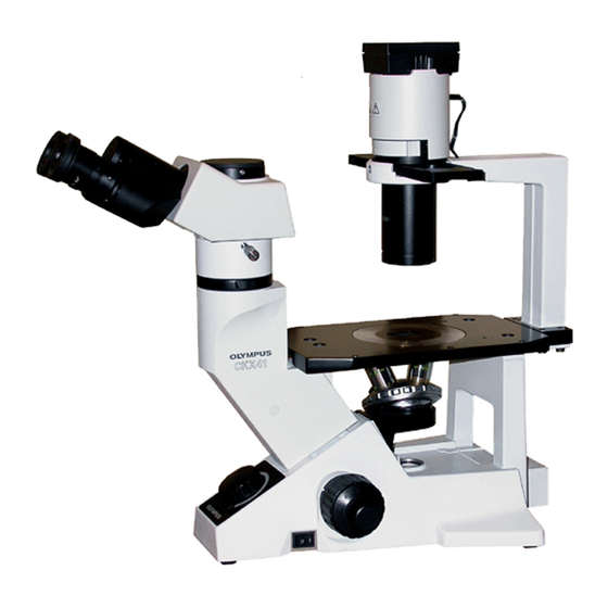
CKX31/CKX41
NTRODUCTION
The CKX31/CKX41 is a culture microscope newly adopting the UIS optical system and is
placed as the successor to conventional CK30/CK40. In electrical unit, the circuit board
is used, which corresponds to world-wide voltage by built-in voltage changeover switch.
This manual has been written on the premise that the service engineer already has experience
repairing the CK30/40 and observation tube, CH3-BI45. If not, it is necessary to read
thoroughly the procedures of optical axis adjustment in CK30/40 and CH3-BI45 repair
manuals because the explanation of these parts are ommited as a common repair skill.
In optical adjustment section, parfocality adjustmet is mainly explained on D-6 and D-12.
The parfocality is required to adjust precisely due to severe standard compare with CK30/40.
1) For overview of optical adjustment, refer to D-1 and D-2 in the section of repair procedure.
2) Before optical adjustment, refer to jigs used in CKX31/ CKX41on D-4, D-9 and D-10.
3) Since the optical axis adjustment for binocular tube of CKX31 is basically the same as that
of CK30, the adjustment procedure is not written in this manual. Therefore, it is referred to
CK30/CK40 repair manual.
4) The above matter is also applied to CKX41. Therefore, this manual instructs the reference
page in CH3-BI45 repair manual when U-CBI30-2 is repaired.
In case where the other observation tube, which can be combined with CKX41 frame, is
repaired, refer to each corresponding repair manual.
5) Since the descriptions of disassembling and assembling procedures are simplified,
start disassembling according to the order of steps from (A) and assemble in reversed order
while taking care to follow the applied locations of grease/adhesive and remarks.
The "remark" column provides important notes and supplemental information.
(The applied locations of grease/adhesive and adjustment part on components of assembly
are shown in exploded diagram.)
6) Voltage adjustments will be needed when replacing the rheostat ass'y (DZ308500) or
circuit board (DZ308400) respectively. These adjustments can be made by following the
instructions given in this manual.