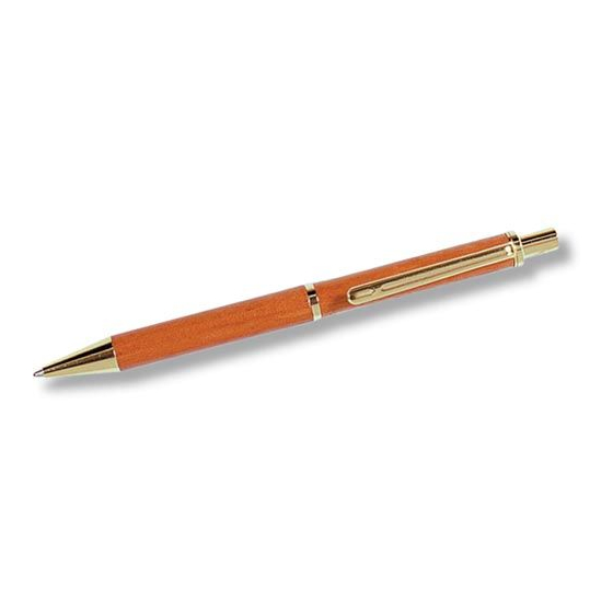
Axminster Pen Kit 지침 - 페이지 2
{카테고리_이름} Axminster Pen Kit에 대한 지침을 온라인으로 검색하거나 PDF를 다운로드하세요. Axminster Pen Kit 2 페이지.
Axminster Pen Kit에 대해서도 마찬가지입니다: 지침 (2 페이지)

Instructions for 10ct Click Pen Kit...
Kit No. 400316
10ct European Pen Kit (A logo)
Pictures of the finished sample articles, in both timber and acrylic, can be found in our
catalogue in the 'Woodturning Projects' Section.
Below is a list of the items required to make the finished items from the purchased
kits. (Not including the body blanks). If you do not possess these items we have
offered our catalogue stock code numbers alongside the items as a quick guide. We
have tried to include everything in the list, although we realise that many
woodturners will already have most of them.
Required items...
Alternatives are listed to cater for different lathe configurations.
Deluxe Pen Mandrel 1MT
Deluxe Pen Mandrel 2MT
60˚ Live Tail Stock Centre 1MT
60˚ Live Tail Stock Centre 2MT
60˚ Live Tail Stock Centre 3MT
Bushing Set (4 pieces)
8mm Drill Bit (we recommend the Colt Pen Drill)
Axminster Universal Barrel Trimmer
2 Part Rapid Epoxy Resin Adhesive
Alternative Zap-A-Gap Adhesive (Cyanoacrylate)
Recommended Accessories...
Quick Action Pen Blank Vice
Pen Blank Sizing and Cutting Jig
Axminster Pen Assembly Press
What's in the Kit...
(a)
2 Brass Tubes (50mm Long)
1 Threaded Insert Bush
(b)
1 Lower Joining Bush
1 Tip
1 Pen Clip
(c)
1 Ballpoint Refill
1 Pen Clip Securing Cap
(d)
1 'Click' Mechanism
1 Silver Tube
(e)
1
a
f
b
g
Preparing the Bodies...
Using 16mm (5/8") Square stock; cut the blanks to the length of the brass tubes
adding 2-3mm to allow for trimming. The Pen Blank Sizing and Cutting Jig makes this
process very much easier.
Drill an 8mm diameter hole through the centre of the blank. Care must be taken not
to force the drill bit, (this may cause it to 'wander' from the centre line), and
Order No:
remember to back out the drill frequently to clear the debris from the hole. If you are
211322
using a pillar drill the Quick Action Pen Blank Vice is a very useful accessory for this
211323
task, it ensures that the blank is held upright and firmly in position. Moreover, if the
vice is clamped to the table of the drill, it will provide accurate repeatability for all the
340202
blanks that require drilling.
340203
340204
When the hole is drilled, spread the adhesive randomly over the brass tube and insert
310380
the tube into the blank using a twisting motion to ensure the glue is spread evenly
between the two surfaces. Over insert the tube into the blank by approximately 1mm
702555
giving an allowance for the blank to be trimmed to size and the excess glue to be
700265
removed (See Fig 1).
340282
990095
Fig 1
600771
600623
200205
Brass tube
(f)
Warning. If you are using cyanoacrylate adhesive, exercise extreme caution and
(g)
do not allow the adhesive to come into contact with the skin. If this happens
(h)
keep the affected area from contact with any other surface, until the glue has
hardened or you can treat the area with a softening agent similar to Zap Z-7
(i)
Debonder (990099), and you can remove the glue.
Allow the adhesive to dry thoroughly.
Using the Barrel Trimmer trim the ends of the blanks squarely and neatly to the ends
of the brass tubes; this will also remove any excess glue that may have exuded from
the joint. Take care not to undercut the brass tubes.
d
Slide a mandrel spacer onto the shaft. Add a bush from the Bushing Kit. Mount a Pen
c
Body next, add two more bushes (back to back) then the other Pen body, finally the
last bush of the set. Add the mandrel spacer and the locking nut; tighten finger tight.
Mount the assembly onto your lathe. Tighten the lock nut to allow the assembly to
be turned without moving (See Fig 2).
h
Fig 2
e
i
Morse taper shaft
Fig 3
Do not overtighten, this may cause the assembly to distort, the bodies to split, strip
the thread on the lock nut, etc. Similarly do not advance the tailstock centre with too
much force. The current bulk of the blanks may be adding strength to the assembly
but as the body diameters are reduced, too much force on the mandrel may cause it
to distort/bow. Turn the main bodies, finish and sand to the guide diameters of the
pen bushings. Remove the finished bodies from the pen mandrel (See Fig 3).
Note. The Axminster Pen Assembly Press (200205) is a very useful accessory for
these operations, as it gives greater control over the applied force and keeps
the components in line (See Fig 4).
Blank
Fig 4
ø
8mm
Zap Z-7
In the illustration that follows the upper and lower body of the pen have dissimilar
Debonder
profiles; and the instruction is oriented to this fact. If your body profiles are the same
then the instruction applies to either, ensure however, that the correct parts are
fitted to each body. Line up the Lower Pen Body components as shown in (Fig 5).
Make sure the body and the tip (g) are aligned and gently but firmly, press the
Ballpoint End Tip home. (Force Fit), repeat at the other end with the lower joining
bush (b) (thread out).
Fig 5
2
Turning the Bodies...
Mandrel bush
Pen bodys
Bushing
Live tail stock centre
General Assembly...
Axminster Pen Assembly Press
Lower body
b
3
g
Bushing
Mandrel spacer
Locking nut
Continues Over....
