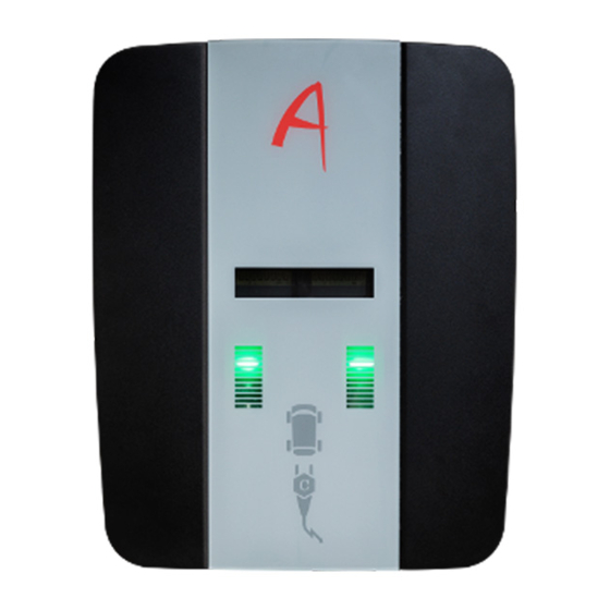
Alphatec Wallbox Power 기술 사양 - 페이지 12
{카테고리_이름} Alphatec Wallbox Power에 대한 기술 사양을 온라인으로 검색하거나 PDF를 다운로드하세요. Alphatec Wallbox Power 19 페이지.

Handbuch | Wallbox Power
Einstellen des Maximal-Stroms
Schritt für Schritt
1.
Stellen Sie sicher, dass die Stromquelle
abgesteckt ist.
2.
Drehen Sie den Drehschalter mit einem
kleinen Schraubendreher auf die korrekte
Position (vgl. Tabelle).
3.
Schließen Sie die Abdeckung wieder.
4.
Stellen Sie die Stromzufuhr wieder her.
Die Einstellungen werden nach dem Neustart
automatisch übernommen, wie im Falle
eine Stromausfalles.
5.
Verbinden Sie den Ladestecker mit dem
Test-Simulator oder reinem Fahrzeug,
das beim Laden den Stromfluss anzeigt.
6.
Gleichen Sie die Einstellungen mit dem
tatsächlichen Stromfluss ab.
LED-Anzeige der
Einstellungen während
der Boot-Sequenz:
Die blaue Blinksequenz
zeigt die Zehnerstelle,
die grüne Blinksequenz
zeigt die gewählte
Einerstelle des Stromes.
z. B.
32 Ampere = 3 lange
Blinkzeichen blau und
2 Blinkzeichen grün (kurz)
15A = 1 x blue / 5 x green
22
Technische Änderungen unter Vorbehalt | Stand 03/2022 | DB9.0043 | DB9.0044
3 phase
1 phase
General
1 - 6A
A - 18A
0
2 - 7A
B - 20A
3 - 8A
C - 25A
4 - 9A
D - 32A
5 - 10A
6 - 13A
E - free
7 - 14A
8 - 15A
F - slave
9 - 16A
Manual | Wallbox Power
Maximum current setting
Step by step
1.
Ensure that the power source is disconnected.
2.
Turn the rotary switch with a small srewdriver
to the correct position (see table).
3.
Close the cover.
4.
Enable the power source. The settings
will be active after a reboot of the
charger after a power-off.
5.
Connect the charger to the test-simulator or
a car which shows the current while charging.
6.
Control the settings with the real current.
LED display of the
settings during the
boot sequence:
The blue flashing
sequence shows the
tens digit, the green
flashing sequence
shows the one digit
of the current.
z. B.
32 Ampere = 3 lange
Blinkzeichen blau und
2 Blinkzeichen grün (kurz)
15A = 1 x blue / 5 x green
Technische Änderungen unter Vorbehalt | Stand 03/2022 | DB9.0043 | DB9.0044
3 phase
1 phase
General
1 - 6A
A - 18A
0
2 - 7A
B - 20A
3 - 8A
C - 25A
4 - 9A
D - 32A
5 - 10A
6 - 13A
E - free
7 - 14A
8 - 15A
F - slave
9 - 16A
23
