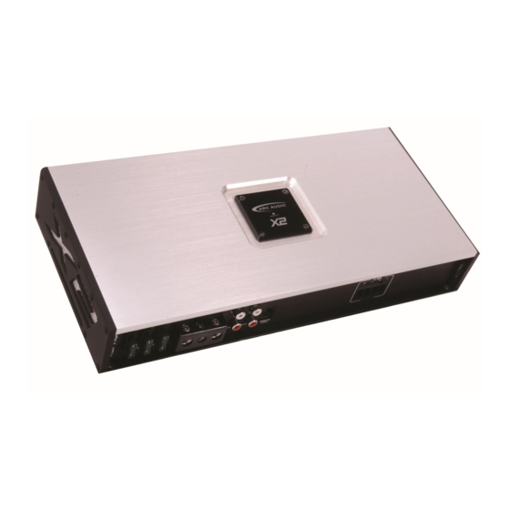
ARC Audio X2 650.1 소유자 매뉴얼 - 페이지 6
{카테고리_이름} ARC Audio X2 650.1에 대한 소유자 매뉴얼을 온라인으로 검색하거나 PDF를 다운로드하세요. ARC Audio X2 650.1 11 페이지. Class d monoblock amplifier

Load Impedance
All ARC Audio Amplifiers are designed as voltage-based
Power Amplifiers. This means, the amount of power
FUSE 30 AMP X 2
produced to the speaker is dependent on the impedance of
the connected speaker(s). Reducing the impedance of the
speaker(s) will increase the amount of power produced by the
amp, within certain design limits.
With respect to the X2 Series Monoblock amplifiers, your
installer may connect a subwoofer or combination of
PWR \ PROT
subwoofers with a total combined impedance of no less than
1 Ohm.
The X2 1100.1 and X2 2500.1 include two positive and two
TURN ON
negative speaker terminals. These terminals are connected
+12 V
GND
together inside the amp. The amp sees the net load
connected to both terminals simultaneously.
WARNING: These amplifiers will not operate and could be
damaged if used in the wrong configuration. At no time should
they be operated below 1 Ohm.
Note: None of the X2 Series Monoblock amplifiers are
designed to be strapped or bridged together to power a single
speaker voice coil. Under no circumstances should the output
of any X2 Series Amplifier be connected to anything other
than a speaker voice coil or passive crossover network.
Speaker Output Connections
The X2 650.1 and X2 1100.1 are equipped with set of
removable plug-style terminals for speaker wire connections
up to 12 AWG.
Due to its massive current delivery capabilities, the X2 2500.1
uses a four-position 8 AWG terminal block for speaker wire connections. Speaker wire is secured in place using #2
Phillips set screws. Be conscious of the size of speaker wire you choose when using this amplifier. I can produce more
than 50 amps of current from the speaker terminals.
Make all speaker wire connections carefully and neatly. Strip the wire back 5/16", twist the exposed leads together
tightly, and insert them into the block terminal while being careful that there is no loose or frayed strands of wire touching
adjacent wires or connections. Tighten the set screw on the terminal until the wire is held in place securely. The amplifier
will go into protection if the wires ever come in contact
Power, Ground and Turn-On Connections
The X2 650.1 and X2 1100.1 amplifiers feature a terminal
block that is designed to accept 4 AWG power and ground
connections. The X2 2500.1 is designed for use exclusively
with 0/1 AWG power wire. We recommend the use of pure
copper power and ground wires in order to achieve the most
reliable connections and efficient current delivery.
X2 2500.1 Power Wiring Note: Due to the immense current
consumption capabilities of this amplifier, it s recommended
that your run both power and ground wires directly to the
battery. You may need to upgrade your battery, add additional
batteries or upgrade your charging system to supply this amplifier with enough voltage and current for it to produce it's full
2500 rated output.
The Turn On input should be connected to the amplifier +12V DC remote turn-on output of your after-market source unit.
In most cases this is a blue wire with a white stripe. Note: On some source units, there are power antenna AND remote
turn-on wires. If you only hear audio when listening to the AM/FM tuner, your amp may connected to the wrong wire.
Page 6
SIGNAL
DC
DETECT
DETECT
OFF
CROSSOVER
FREQ Hz
TURN ON
+12 V
GND
INPUT
SLAVE IN
REMOTE
LEVEL
SLAVE OUT
INPUT
SLAVE IN
REMOTE
LEVEL
SLAVE
OUT
FUSE 30 AMP X 3
SUB
1Ω MIN
SUB
1Ω MIN
SUB
1Ω MIN
INPUT
HIGHPASS
SELECT
FREQ Hz
50
2CH
4CH
500
AUTO
SENSE
DO NOT BRIDGE
OR STRAP
50
SIGNAL
DETECT
OFF
500
DC DETECT
HIGHPASS
FREQ Hz
TURN ON
+12V
GND
CH3/4
HP RANGE
110
MIN
FULL
X1
HIGH
X10
MAX
330
BANDPASS
LP RANG
110
110
50
OFF
X1
ON
X10
500
330
330
LOWPASS
FREQ Hz
CH1/2
2 CH INPUT
CH1
CH3
C
CH2
CH4
C
BRIDGED
INPUT
