DigiDesign 96i I/O 매뉴얼 - 페이지 10
{카테고리_이름} DigiDesign 96i I/O에 대한 매뉴얼을 온라인으로 검색하거나 PDF를 다운로드하세요. DigiDesign 96i I/O 16 페이지. 16-input, 2-output digital audio interface features 24-bit analog-to-digital (a/d) and digital-to-analog (d/a) converters
DigiDesign 96i I/O에 대해서도 마찬가지입니다: 빠른 매뉴얼 (13 페이지), 매뉴얼 (20 페이지)

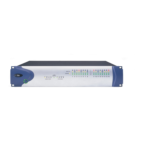
Loop Master LED
The LOOP MASTER LED indicates which
Pro Tools|HD audio interface is the master
Pro Tools peripheral. Loop Master defaults to
the first Pro Tools|HD I/O connected to the
"core" Pro Tools|HD card. On Pro Tools|HD (for
PCIe) this is the Accel Core card. On
Pro Tools|HD (for PCI) this is the HD Core card.
Loop Master will always be lit in systems with a
single interface.
In expanded systems, only one Pro Tools|HD
I/O can be Loop Master at a time. When you
change the clock source to an external clock on
a particular Pro Tools|HD I/O or a SYNC I/O,
that Pro Tools|HD I/O (or SYNC I/O) will auto-
matically become the Loop Master and all other
Pro Tools|HD I/Os in the chain will be switched
to Loop Slave mode.
Sync Mode LEDs
The SYNC MODE LEDs indicate the current
Pro Tools Clock Source and Sync mode. Choices
include the following:
INT (Internal) Indicates the 96i I/O is the
Pro Tools clock master.
DIG (Digital) Indicates the 96i I/O S/PDIF port is
providing master clock to Pro Tools.
LOOP (Loop Sync) Indicates 96i I/O is in Loop
Slave mode, and is clocking to the current Loop
Master device (which will either be another
Pro Tools|HD audio interface, a Digidesign
SYNC I/O, or equivalent device). See also "Loop
Master LED" on page 6.
EXT (External) Indicates the 96i I/O EXT
CLOCK IN port is providing master clock to
Pro Tools.
6
96i I/O Guide
For more information on Pro Tools clock op-
tions, see the Pro Tools|HD Getting Started Guide.
Input and Output LEDs and Meters
16 sets of four-segment LEDs indicate signal
level for each of the 96i I/O input channels.
These LEDs are calibrated at –42 dB, –18 dB,
–6 dB, and 0 dB, respectively, referenced to Full
Scale digital.
Full Scale digital (0 dBFS) does not always
indicate signal clipping levels. Use the on-
screen meters in Pro Tools to determine
whether a signal is clipping. For more infor-
mation, see the Pro Tools|HD Getting
Started Guide .
Two additional LEDs, located to the left of the
meters, indicate whether the meters display in-
put or output levels; the meters indicate input
levels by default, and can be switched from
within the Hardware Setup dialog in Pro Tools.
