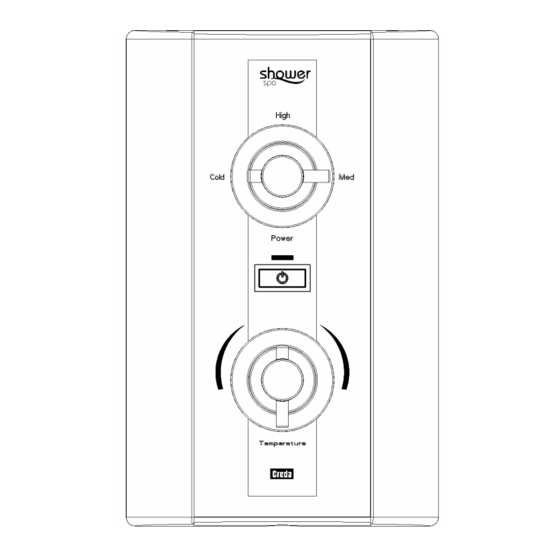
Creda Shower SPA 설치 및 사용자 설명서 - 페이지 4
{카테고리_이름} Creda Shower SPA에 대한 설치 및 사용자 설명서을 온라인으로 검색하거나 PDF를 다운로드하세요. Creda Shower SPA 8 페이지. Electric shower

HOW TO INSTALL YOUR SHOWER SPA
WARNING: ALL WIRING AND INSTALLATION MUST BE
SUPERVISED BY A SUITABLY QUALIFIED PERSON.
WARNING: DO NOT INSTALL THIS SHOWER WHERE IT MAY BE
SUBJECTED TO FREEZING CONDITIONS
We recommend that the installation is done in the following sequence.
a. Fixing the shower to the wall
b. Plumbing c. Electrical connections
a. FIXING THE SHOWER TO THE WALL
1. Position the riser rail at a convenient height for majority of users as
detailed in Diagram 1 and mark its position.
2. Position the heater so that the top of the unit is horizontal and level
with, or a maximum of 0.6 metres (2ft) below the top of the
riser rail. Choose a flat piece of wall to avoid the possibility of
distorting the backplate, as this may make the front cover a poor fit.
3. Adjust the position to get the most convenient arrangement taking
the following into account.
•
The heater must not be mounted in the direct spray from the handset.
•
The handset must not be able to come into contact with used water in the cubicle, bath or
basin. If it can, then a vacuum breaker must be fitted (available from us if required).
4. Fix the riser rail with screws provided.
The fixing holes at the base of the brackets will be disclosed by removing the plastic fronts.
See Diagram 5 and instructions supplied with accessories for further details.
5. If you have not yet done so, remove the front cover assembly by undoing the retaining screws at
the top and bottom of the unit and lifting the cover off.
6. Your shower unit not only accepts services from the top, bottom or rear.
It also accepts services from the left or right hand side of the unit.
Decide the position of the electrical cable into the unit.
If top entry is chosen, cut away the walls in the backplate as shown in Diagram 2a.
If bottom entry is chosen, cut away
the walls in the detachable bottom
section as shown in Diagram 2b.
The detachable bottom section is
secured to the backplate by 2 screws.
7. Decide the position of entry of the
cold water pipe into the unit.
If top entry is chosen,
cut away the backplate as shown in
Diagram 2a.
If bottom entry is chosen, cut away the
walls in the detachable bottom section
as shown in Diagram 2b.
If rear, please read the section on plumbing.
To aid installation, you may find it convenient to move the flexible pressure relief valve outlet
assembly by removing the two securing screws.
If you do, please ensure that they are fully tightened on re-assembly (see Diagram 2b).
4
WHAT TO DO IF THINGS GO WRONG (2)
PROFESSIONAL SERVICE
If the previous "Self Help" checks fail to restore the performance, you should seek professional help.
The person who installed the shower is probably the best one to investigate and correct it and is
certainly the person to contact if you have had a problem in the guarantee period.
The following additional checklist is provided for the benefit of the qualified service person.
WARNING: SWITCH OFF THE ELECTRICITY AT THE LOCAL ISOLATOR
BEFORE REMOVING THE COVER TO MAKE CHECKS
Water too HOT
Water flow restricted by blockage in filter of solenoid valve.
Replace the solenoid valve.
Water too COLD
Check circuit through thermal cut-out.
Check circuit through microswitches on the pressure switch & power selector.
Check each element circuit.
Check tightness of electrical connections.
No control over
Check control knob is correctly engaged onto the stabiliser valve drive gear.
water flow
Undo headworks of stabiliser valve.
Check stabiliser is in place and remove any debris in valve then re-assemble.
Water discharges
Check for cause of high pressure and remove it.
from pressure
Blockage on outlet e.g. blocked shower handset.
relief valve
Replace the pressure relief disc (not covered by guarantee).
Water does not
Check circuit through solenoid coil. If defective then replace.
flow when button
Check circuit through push button switch. If defective then replace.
"B" is pressed.
Power supply not reaching shower.
CREDA AFTER SALES SERVICE
We offer a technical advisory service on the telephone to installers and other customers with
problems in the field.
RING 0844 372 7766 (UK ONLY)
Some spare parts (see Page 11) can be supplied against Credit or Debit cards.
RING 0844 372 7750 (UK ONLY)
Remember to quote the exact type of shower, as
written on the front of the shower and on this leaflet.
The model and serial number are located on the
bottom face of the shower.
Make a note of those numbers here, and be sure
to quote them if you call for advice.
Model Number: 53-67_ _ _ _ _ _ _
Serial Number: _ _ _ _ _ _ _ _ _ _ _
Note: You may be charged for a service call
if you do not have the serial number.
13
