ABB 695FI 작동 지침 - 페이지 6
{카테고리_이름} ABB 695FI에 대한 작동 지침을 온라인으로 검색하거나 PDF를 다운로드하세요. ABB 695FI 16 페이지. Field indicator
CALIBRATION PROCEDURE
The field indicator housing may be grounded using the
external earth connection.
When the wiring connections are complete plug the meter
and check that the cover O-ring gasket is properly in place,
screw on the cover and tighten.
WARNING - For Hazardous Areas installations,the
connection of cables and conduits to the indicator shall
be made in accordance with the requirements of the
relevant type of protection. Cables and cable-glands
must be in accordance with the type of protection.
Unused openings for connection shall be closed with
blanking elements suitable for the relevant type of
protection. With the exception of intrinsically safe
indicators, the means provided for this shall be such
that the blanking element can be removed only with
the aid of tools. The blanking elements must be cer-
tified for the type of protection. See standards either
EN 60079-14 or IEC 79-14. The indicator connections
must also guarantee the degree of protection of the
indicator enclosure, e.g. IPxx according to EN 60529
standard (or IEC60529).
WARNING - For Hazardous Areas installa-
tions, when the ambient temperature is higher than
70°C/158°F, the cable used for the connections must be
suitable for 5°C/41°F above the ambient temperature.
- 6 -
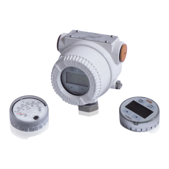
ANALOG OUTPUT METER CALIBRATION
The analog output meter provides a 90° scale indication.
It has either a 0 to 100 linear scale or a 0 to 10 square root
scale or special on request.
The calibration of the analog type meter, only involves
zeroing. Fig. 5 shows the location of the zero adjustment.
Fig. 5 - 90° Analog meter
The calibration is quite simple using one of the following
methods:
- with the loop unpowered adjust the zero screw to read
exactly the true zero mark on the scale.
- with the transmitter transmitting 4 mA adjust the zero screw
to read exactly the live zero of the scale.
Zero
adjustments