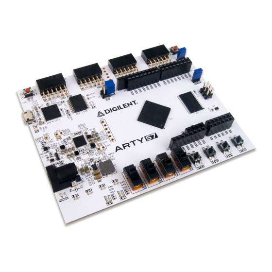
Digilent Arty S7 참조 매뉴얼 - 페이지 6
{카테고리_이름} Digilent Arty S7에 대한 참조 매뉴얼을 온라인으로 검색하거나 PDF를 다운로드하세요. Digilent Arty S7 14 페이지.

(https://reference.digilentinc.com/_detail/arty/arty_xsdk.png?
id=reference%3Aprogrammable-logic%3Aarty-s7%3Areference-manual)
you design your soft SoC configuration for the Arty S7 you can start
writing programs for it. This is done by exporting your SoC design out of
Vivado IPI and into the Xilinx Software Development Kit (XSDK), an
Integrated Development Environment (IDE) for designing/debugging
MicroBlaze programs in C and C++. After the IPI to XSDK handoff,
XSDK is automatically configured to include libraries and examples for
the peripheral blocks you've included in your SoC. At this point,
programming the Arty S7 is very similar to programming other SoC or
microcontroller platforms: Programs are written in C, programmed into
board over USB, and then optionally debugged in hardware. Soft SoC
configurations and MicroBlaze programs can also be loaded into the
16MB non-volatile program memory so that they execute immediately
after Arty S7 is powered on.
Although the Arty S7 is particularly well suited for Microblaze Soft SoC
designs, it can also be programmed with a Register-Transfer Level (RTL)
circuit description like any other FPGA development platform. This
Functional Description
1 Power Supplies
The Arty S7 board requires a 5 volt power source to operate. This power source can come from the Digilent USB-JTAG port (J10) or it can be derived from a 7 to 15 Volt DC power
supply that's connected to the Power Jack (J12) or Pin 8 of Header J7. Header JP13, labeled "5V SELECT", is used to determine which source is used.
A power-good LED () (LD9), driven by the "power good" (PWRGD) output of the ADP5052 regulator, indicates that the board is receiving power and that the onboard supplies are
functioning as expected. If this LED () does not illuminate when an acceptable power supply is connected and selected with JP13, please contact your distributor or
Support
(http://forum.digilentinc.com)
An overview of the Arty S7 power circuit is shown below.
(https://reference.digilentinc.com/_detail/reference/programmable-logic/arty-s7/arty-s7-power.png?id=reference%3Aprogrammable-logic%3Aarty-s7%3Areference-manual)
Circuit.
The USB port can deliver enough power for the vast majority of designs. However, a few demanding applications, including any that drive multiple peripheral boards, might require
more power than the USB port can provide. Also, some applications may need to run without being connected to a PC's USB port. In these instances an external power supply or
battery pack can be used.
An external power supply can be used by plugging into Power Jack J12 and installing a jumper in the "REG" position on Header JP13. The supply must use a coaxial, center-positive
2.1mm (or 2.5mm) internal-diameter plug, and provide a voltage of 7 to 15 Volts DC. The supply should provide a minimum current of 1 amp. Ideally, the supply should be capable of
providing 36 Watts of power (12 Volts DC, 3 amps).
An external battery pack can be used by connecting the battery's positive terminal to pin 8 of J7 (labeled VIN) and the negative terminal to pin 7 of J7 (labeled GND ()), as shown in
Figure 1.2. In order to use the battery pack as the board's power source a jumper must be installed in the "REG" position on Header J13. The battery must provide a voltage between 7
and 15 volts DC, and should NOT be installed while there is a supply connected to Power Jack J12.
After
for further help.
design flow requires that you describe your RTL circuit using an HDL within
Vivado, and it does not use the Vivado IPI or XSDK tools. Designing this
way has many advantages, but is very unlike programming a single board
computer, and instead is used by those familiar with FPGA design or
interested in designing and implementing a digital circuit that doesn't contain a
processor.
Digilent
Figure 1.1. Arty S7 Power
