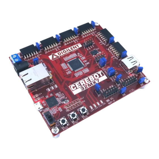
Digilent Cerebot 32MX7 참조 매뉴얼 - 페이지 4
{카테고리_이름} Digilent Cerebot 32MX7에 대한 참조 매뉴얼을 온라인으로 검색하거나 PDF를 다운로드하세요. Digilent Cerebot 32MX7 18 페이지.

Cerebot 32MX7 Reference Manual
The voltage on the VCC5V0 bus will be 5V
when the board is being operated from USB
power or an external regulated 5V supply. If a
different voltage external supply is used, that
voltage will appear on the VCC5V0 bus.
Note: The signal labeled DBG5V0 on the
schematic comes from the debug USB
connector. If the debug USB connector is not
connected to a live USB port, this voltage will
not be present and the debug circuit is not
involved in turning on board power. In this
case, the board power is turned on when the
power switch is placed in the ON position.
The PIC32 microcontroller and on-board I/O
devices operate at a supply voltage of 3.3V
provided by the VCC3V3 bus. The regulated
voltage on this bus is provided by a Microchip
MCP1726 Low Dropout voltage regulator,
IC10. This regulator is capable of providing a
maximum of 1A of current. The PIC32
microcontroller will use approximately 85mA
when running at 80MHz. The SMSC LAN8720
Ethernet PHY consumes approximately 45mA
when operating at 100Mbps. The Microchip
MCP2551 CAN transceivers can draw up to
75mA each when operating the CAN busses.
The other circuitry on the board will draw 10-20
mA. The remaining current is available to
provide power to attached Pmods and I2C
devices. The voltage regulator is on the
bottom of the board, approximately under the
"3" in the Cerebot 32MX7 logo, and will get
warm when the amount of current being used
is close to its limit.
The Cerebot 32MX7 can provide power to any
peripheral modules attached to the Pmod
connectors, JA-JF, and to I2C devices
powered from the I2C daisy chain connectors,
J7 and J8. Each Pmod connector provides
power pins that can be powered from either the
switched main power bus, VCC5V0, or
regulated voltage, VCC3V3, by setting the
voltage jumper block to the desired position.
The I2C power connectors only provide
regulated voltage, VCC3V3.
USB Interface
www.digilentinc.com
Copyright Digilent, Inc. All rights reserved. Other product and company names mentioned may be trademarks of their respective owners.
The PIC32MX795 microcontroller contains a
USB 2.0 Compliant, Full Speed Device and
On-The-Go (OTG) controller. This controller
provides the following features:
USB full speed host and device support
Low speed host support
USB OTG support
Endpoint buffering anywhere in system
RAM
Integrated DMA to access system RAM
and Flash memory.
When operating as a USB device, the Cerebot
32MX7 can be used as a self powered device
or as a bus powered device. To operate as a
self powered device, an external power supply
should be connected to one of the external
power connectors (J17 or J18) and a shorting
block placed on the center, "EXT" position of
J16. The external power supply must be a
regulated 5V supply. To operate as a bus
powered device, the shorting block should be
placed in the USB Device position, "USB", on
J16.
Connector J19, on the bottom of the board in
the lower right corner is the Device/OTG
connector. This is a standard USB micro-AB
connector. Connect a cable with a micro-A
plug (optionally available from Digilent) from
this connector to an available USB port on a
PC or USB hub for device operation.
When operating as a USB host, the Cerebot
32MX7 must be externally powered. Connect
a regulated 5V power supply to one of the
external power connectors (J17, or J18) and
ensure that the shorting block is in the center,
"EXT" position of J16. The power supply used
must be a regulated 5V supply. The Cerebot
32MX7 board provides power to the attached
USB device when operating as a host, and the
USB specification requires the use of a 5V
power supply. NOTE: Providing a voltage
greater than 5V can damage the Cerebot
32MX7 board and/or the USB device being
used.
Jumper JP10 is used to route power to the
host connector being used. Place the shorting
page 4 of 17
