FIAMA PFA5000T 사용자 설명서 및 유지 관리 - 페이지 5
{카테고리_이름} FIAMA PFA5000T에 대한 사용자 설명서 및 유지 관리을 온라인으로 검색하거나 PDF를 다운로드하세요. FIAMA PFA5000T 6 페이지. Linear potentiometer wire-transducer with analgoue output
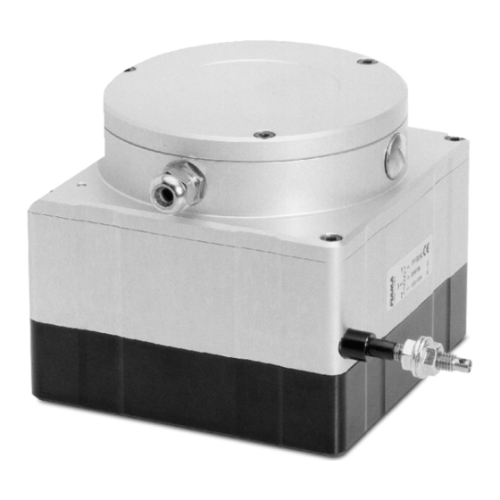
Potentiometric wire linear transducers
Connections entries and exits
Physically separate the entry wires from those of the power supply, the exits, and the power connections;
use twined and shielded wires with the display connected to the earth only at one point.
Connect the exits of adjustments, alarms (meters, electro valves, motors, ventilators, etc.) assembling units
RC (resistance and condenser in series) parallel to the charged inductive that work alternatively.
To reach the terminal block unscrew the 3 screws of the cover.
6
5
4
Analogue output calibration
The factory calibration previews an analogue output of 0-10V with 0V when the cable is all inside and 10V
with the cable all outside. It is possible to modify this calibration to refer all the range of the analogue output
to the stroke of the transducer really used or to change to the direction or the type (tension/current) of the
output. In all versions are available analogue outputs in tension and current but only one can be calibrate
correctly. It is not possible to have both outputs calibrate because the calibration of one excludes the other.
Before the calibration it is necessary to position the bridges J1 and J2 according to the direction of the
output: for increasing analogue output with the cable of the transducer in drawing the bridges go in position 2
(0Volt or 4mA in output with the cable all inside); for decreasing analogue output with the cable of the
transducer in drawing the bridges go in position 1 (10Volt o 20mA in output with the cable all inside).
To calibrate the output in voltage link a voltmeter on the terminals 3 (+) and 5 (-) of the terminal block.
To calibrate the output in current link a milliammeter on the terminals 4 (+) and 5 (-) of the terminal block.
Position the cable of the transducer on minimum position of the analogue output then turn the trimmer T1 to
bring the value of the output to 0V for the output in tension or 4mA for the out put in current (turn T1
clockwise to increase the output).
Position the cable of the transducer on the position that has to corresponds to the maximum of the analogue
output and turn the trimmer T2 to bring the output to 10V for the output in tension or 20mA for the output in
current (turn T2 clockwise to increase the output).
Bring the cable back to the minimum position and readjust T1, go back to the maximum position and readjust
T2.
Repeat the readjustments until reaching a perfect calibration.
The electric cable can goes out in two orthogonal directions: move the press-cable in the required position
and cover the other.
For electrical connections always use a shielded cable (with shield connected to GND)
which must be kept separate from power lines or sources of electromagnetic interference.
Make the electrical connections with due care and attention: a failure due to a connection
error renders the guarantee null and void
The power supply must fall within the admissible range, a value exceeding this range or an
alternate current could damage the unit.
Data: 13/01/16
J1
T1
1
2
T2
J2
3
2
1
File: PFA_T_ing.doc
PFA3000T-12000T
1
GND
negative power supply
2
+24V
positive power supply
3
Vout
analogue voltage output 0-10V
4
Iout
current voltage output 4-20mA
5
Com
common analogue output
6
not connected
Pagina: 5 di 6