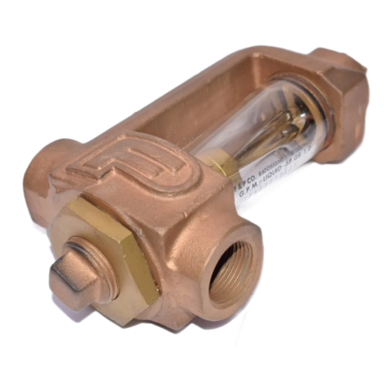
ABB RATOSIGHT 10A2235 사용 설명서 - 페이지 3
{카테고리_이름} ABB RATOSIGHT 10A2235에 대한 사용 설명서을 온라인으로 검색하거나 PDF를 다운로드하세요. ABB RATOSIGHT 10A2235 5 페이지. Variable area flowmeters

Installation
The RATOSIGHT flow rate indicator is normally fur-
nished for horizontal connections. However, vertical
connections or combination horizontal-vertical con-
nections may be made by changing the locations of
the pipe plugs. Thus an over alarm extension can be
added to the Meter using a horizontal outlet. If the
Meter has a vertical inlet, a nipple and union should
be added to facilitate future removal of the float, The
various piping arrangements are shown in Figure 2.
Refer to Figure 4 for the outline dimensions of the
Meter. Install the Meter in the piping system so that
the tube is vertical. The Meter should be as free as
possible from piping strains. When installing large
indicators, use brackets or piping supports to elimi-
nate piping strains.
Operation
Start flow thru the Meter slowly to avoid excessive
flow surges which might damage the float or tube.
Flow rate is read from the scale at a point opposite
the grooved horizontal line on the float. When milli-
meter or other special scales are furnished, a cali-
bration curve may be supplied. By entering the
indicated value on this curve, the actual flow rate
can be obtained. If an alarm extension has been
furnished, refer to the appropriate Instruction Man-
ual to set the alarm point.
Maintenance
Normal maintenance consists of cleaning the float
and tube to maintain good visibility. If the meter inlet
is connected vertically, the inlet piping must be
separated to remove the float. Remove the float and
tube by taking the inlet fitting from the bottom of the
meter.
If the float is received separately from the instru-
ment, insert it in the tube after removing the inlet
fitting. Figure 3 shows the correct float orientation
and the reading edges. If the RATOSIGHT flow rate
indictor is equipped with an alarm extension, com-
plete the wiring as discussed in the alarm's Instruc-
tion Bulletin.
FIGURE 2. PIPING ARRANGEMENTS
WARNING
An operator protective shield is required
when this meter is used for compressed
gases or liquids above their boiling
point. A sheet of polycarbonate can be
used as a shield. Alternately, a series
10A4500 meter with a protective shield
included or an all metal meter can be
substituted.
Caution
Exercise care when removing the inlet
fitting as the float and tube are free to
fall out of the meter body. Clean the
float and tube carefully with a suitable
solvent (detergent and water are usually
satisfactory), then replace the parts. To
disassemble the meter completely,
remove the float as outlined above, then
the outlet adaptor ring may be
withdrawn from the meter body. During
meter re-assembly it is recommended
that new "O" rings be used.
3
