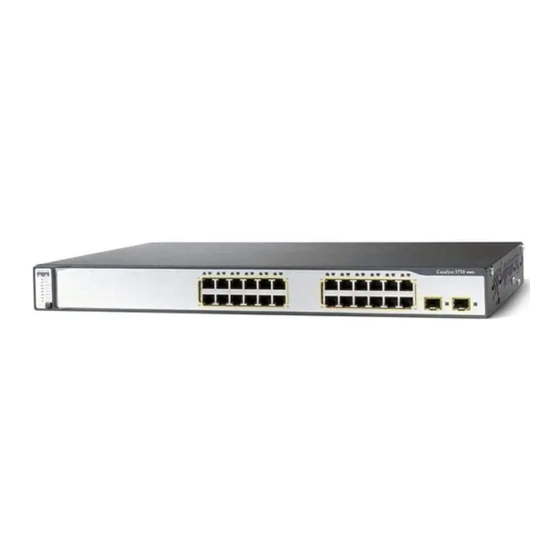
Cisco 3750G - Catalyst Integrated Wireless LAN Controller 시작하기 매뉴얼 - 페이지 21
{카테고리_이름} Cisco 3750G - Catalyst Integrated Wireless LAN Controller에 대한 시작하기 매뉴얼을 온라인으로 검색하거나 PDF를 다운로드하세요. Cisco 3750G - Catalyst Integrated Wireless LAN Controller 49 페이지. Integrated wireless lan controller switch
Cisco 3750G - Catalyst Integrated Wireless LAN Controller에 대해서도 마찬가지입니다: 구성 매뉴얼 (40 페이지)

Verifying Interface Settings and Port Operation
Follow these steps to verify that your interface configurations have been set properly and that the
controller ports are operational.
Enter show interface summary, and press Enter. This display shows the controller interface
Step 1
configurations:
Interface Name
------------------------------ ----
ap-manager
management
service-port
virtual
Link aggregation (LAG) is always enabled for the integrated wireless LAN controller and
cannot be disabled. LAG bundles all of the controller distribution system ports into a
single IEEE 802.3ad port channel. See the Cisco Wireless LAN Controller Configuration
Guide 4.0 or later for more information.
Enter show port summary, and press Enter. This display shows the status of the controller
Step 2
distribution system ports, which serve as the data path between the controller and the
Cisco lightweight access points and to which the controller management and AP-manager
interfaces are mapped.
Pr
Type
-- ------- ---- ------- ---------- ---------- ------ ------- --------- -------
1
Normal
2
Normal
A link status of Up means that the controller ports are fully operational.
STP
Admin
Physical
Stat
Mode
Mode
Forw Enable
Auto
Forw Enable
Auto
Port
Vlan Id
IP Address
--------
--------------
LAG
10
LAG
10
N/A
N/A
N/A
N/A
Physical
Link
Status
Status
1000 Full
Up
1000 Full
Up
Type
-------
10.91.104.99
Static
10.91.104.93
Static
10.10.0.9
Static
1.1.1.1
Static
Link
Mcast
Trap
Appliance
Enable
Enable
Enable
Enable
Ap Mgr
-----
Yes
No
No
No
POE
N/A
N/A
21
