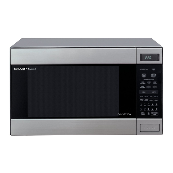
Sharp Carousel R-990C 서비스 매뉴얼 - 페이지 29
{카테고리_이름} Sharp Carousel R-990C에 대한 서비스 매뉴얼을 온라인으로 검색하거나 PDF를 다운로드하세요. Sharp Carousel R-990C 44 페이지. Convection microwave oven
Sharp Carousel R-990C에 대해서도 마찬가지입니다: 운영 매뉴얼 (40 페이지)

6. Re-install the outer case and check that the oven is
operating properly.
1. CARRY OUT 3D CHECKS
2. Disconnect filament lead of transfomer and high voltage
wire lead from magnetron.
3. Take off three (3) screws secured the chassis support
to oven cavity and waveguide.
4. Remove the cooling fan assembly refer to "Cooling Fan
Removal"
5. Carefully remove four (4) mounting screws holding the
magnetron and magnetron air guide to waveguide.
ASYMMETRIC RECTIFIER AND HIGH VOLTAGE RECTIFIER REMOVAL
1. CARRY OUT 3D CHECKS.
2. Remove one (1) screw holding the high voltage rectifier
terminal to the capacitor holder.
3. Disconnect the high voltage rectifier assembly from
the capacitor.
1. CARRY OUT 3D CHECKS.
2. Disconnect the high voltage wire leads and rectifier
assembly from the high voltage capacitor and magnetron.
3. Disconnect filament lead of transfomer from high voltage
capacitor.
4. Disconnect high voltage wire leads of capacitor from
1. CARRY OUT 3D CHECKS.
2. Pull the wire leads from the oven lamp socket by
pushing the terminal hole of the oven lamp socket
withthe flat type small screw driver.
3. Lift up the tab of oven lamp mounting plate holding the
oven lamp socket.
4. Slide the oven lamp socket left-ward.
5. Now, the oven lamp socket is free.
HEATER UNIT ASSEMBLY REMOVAL (HEATING ELEMENT/THERMISTOR)
1. CARRY OUT 3D CHECKS.
2. Disconnect wire leads from oven thermal cut-out,
convection motor, thermistor and heater element.
Remove convection motor ass'y refer to "Convection
Motor Removal No.3 to No.5".
3. Remove eleven (11) screws holding heater duct to the
oven cavity.
4. Release two (2) snap bands holding wire harness to
the thermal protection plate (left).
5. The heater unit is now free.
CONTROL PANEL ASSEMBLY AND CONTROL UNIT REMOVAL
To remove the control panel, proceed as follows:
1. CARRY OUT 3D CHECKS
2. Disconnect connector CN-A, CN-E and CN-F from the
control unit.
3. Disconnect the wire leads from relays RY1, RY2 and RY3.
4. Remove one (1) screw holding the control panel back
plate to the chassis support.
5. Remove the one (1) screw holding the bottom edge of
MAGNETRON REMOVAL
HIGH VOLTAGE CAPACITOR REMOVAL
OVEN LAMP SOCKET REMOVAL
27
NOTE: LIVE(ORANGE) WIRE MUST BE CONNECTED
TO THE CABINET-SIDE OF THE POWER
TRANSFORMER.
When removing the screws hold the magnetron and
magnetron air guide to prevent it from falling.
6. Remove the magnetron from the waveguide with care
so the magnetron antenna should not hit by any metal
object around the antenna
CAUTION: WHEN REPLACING THE MAGNETRON, BE
SURE THE R.F. GASKET IS IN PLACE AND
THE MAGNETRON MOUNTING SCREWS
ARE TIGHTENED SECURELY.
CAUTION: WHEN REPLACING HIGH VOLTAGE REC-
TIFIER ASSEMBLY, ENSURE THAT THE
EARTHING SIDE TERMINAL MUST BE SE-
CURED FIRMLY WITH
SCREW.
transformer.
5. Remove one (1) screw and washer holding the high
voltage rectifier from the capacitor holder.
6. Remove one (1) screw holding capacitor holder to rear
cabinet.
7. Remove the high voltage capacitor from the holder.
Oven lamp
socket
Terminal
Wire lead
Flate type small
screw driver
HEATING ELEMENT AND THERMISTOR
1. Remove two (2) screws holding heating element to
heater duct.
2. Loosen two (2) screws holding holders to heater duct
and take heating element out of heating element holders.
3. Heating element is free.
4. Remove two (2) screws holding thermistor to heater
duct.
5. Thermistor is free.
the back plate to the cabinet base.
6. Remove two (2) screws holding the back plate to the
oven cavity flange.
7. Lift up and pull the control panel forward.
Replacement of individual component is as follows:
CONTROL UNIT AND KEY UNIT
1. Disconnect the flat ribbon cable from the control unit.
R-990C(S)
AN EARTHING
Terminal hole
