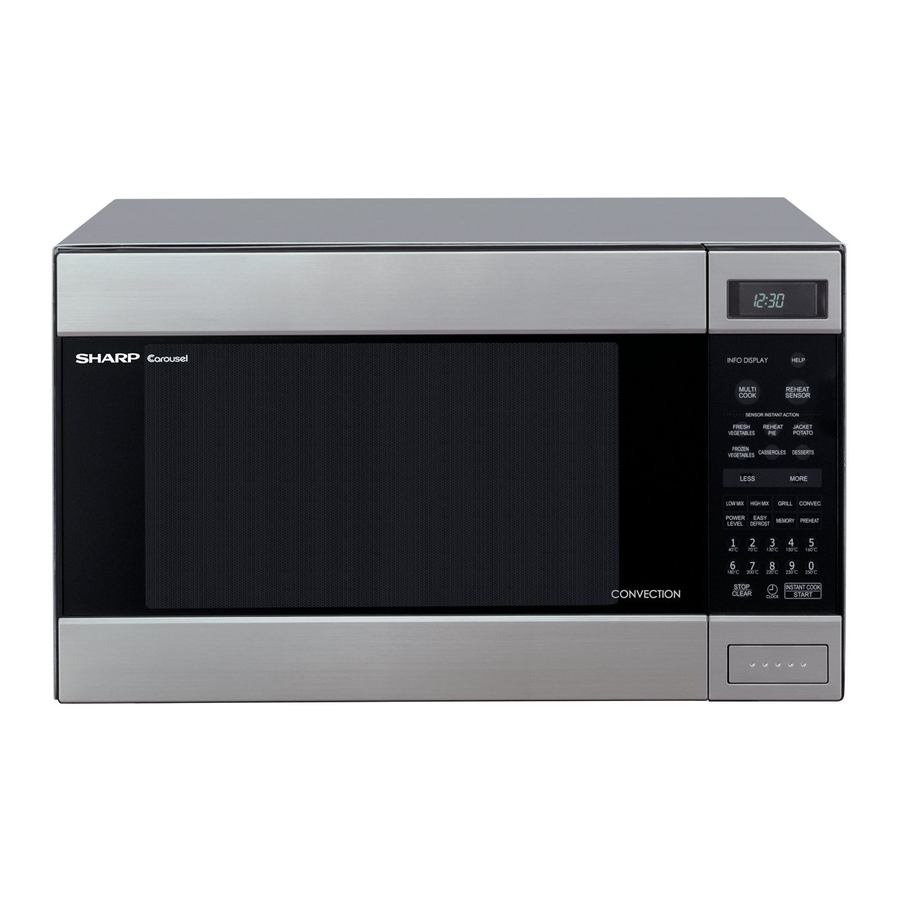
Sharp Carousel R-990K 서비스 매뉴얼 - 페이지 28
{카테고리_이름} Sharp Carousel R-990K에 대한 서비스 매뉴얼을 온라인으로 검색하거나 PDF를 다운로드하세요. Sharp Carousel R-990K 48 페이지. Convection microwave oven
Sharp Carousel R-990K에 대해서도 마찬가지입니다: 운영 매뉴얼 (41 페이지)

R990K(W)
2. HEATING ELEMENT AND THERMISTOR
1. Remove two (2) screws holding heating element to heater duct.
2. Loosen two (2) screws holding holders to heater duct and take
heating element out of heating element holders.
[9] CONTROL PANEL ASSEMBLY AND CONTROL UNIT REMOVAL
1. CARRY OUT 3D CHECKS.
2. Disconnect connector CN-A, CN-E and CN-F from the control unit.
3. Disconnect the wire leads from relays RY1, RY2 and RY3.
4. Remove one (1) screw holding the control panel back plate to the
chassis support.
5. Remove the one (1) screw holding the bottom edge of he back
plate to the cabinet base.
6. Remove two (2) screws holding the back plate to the oven cavity
flange.
7. Lift up and pull the control panel forward.
1. CONTROL UNIT AND KEY UNIT
1. Disconnect the flat ribbon cable from the control unit.
2. Remove the four (4) screws holding the panel frame to the back
plate.
[10] TURNTABLE MOTOR AND/OR COUPLING REMOVAL
1. Disconnect the oven from power supply.
2. Remove one (1) screw holding the turntable motor cover to the
base cabinet and take off the turntable motor cover.
3. Disconnect wire lead from the turntable motor.
[11] CONVECTION MOTOR REMOVAL
1. CARRY OUT 3D CHECKS.
2. .Disconnect wire leads from the convection motor.
Remove the convection fan belt and pulley (M).
3. Remove two (2) screws holding the convection motor mounting
angle to the heater duct and base cabinet.
[12] DAMPER ASSEMBLY REMOVAL
1. CARRY OUT 3D CHECKS.
2. Remove cooling fan motor and magnetron refer to "Cooling Fan
Motor Removal" and "Magnetron Removal".
3. Disconnect wire leads from damper motor and dampers witch.
4. Remove two(2) vanished screws holding damper motor angle to
thermal protection plate (right).
[13] FAN MOTOR REPLACEMENT
1. REMOVAL
1. CARRY OUT 3D CHECKS.
2. Disconnect the wire leads from the fan motor and thermal cut-out.
3. Remove the three (3) screws holding the chassis support to rear
cabinet, control panel back plate and waveguide.
4. Remove one (1) tab holding the fan duct to air guide.
5. Remove the fan motor assembly from the oven cavity.
6. Remove the fan blade assembly from the fan motor shaft according
the following procedure.
1) Hold the edge of the rotor of the fan motor by using a pair of
grove joint pliers.
3. Heating element is free.
4. Remove two (2) screws holding thermistor to heater duct.
5. Thermistor is free.
Now, the control unit and frame assembly are separated.
3. Separate the panel frame and back plate.
4. Remove the three (3) screws holding the control unit to the panel
frame.
5. Lift up the control unit.
6. Replacement of individual component is as follows:
NOTE: 1) Before attaching a new key unit, remove remaining adhe-
sive on the control panel frame surfaces completely with a
soft cloth soaked in alcohol.
2) When attaching the key unit to the control panel frame,
adjust the upper edge and right edge of the key unit to the
correct position of control panel frame.
3) Stick the key unit firmly to the control panel frame by rub-
bing with soft cloth not to scratch.
4. Remove the two (2) screws holding the turntable motor to the
mounting plate of the oven cavity bottom.
5. Pull the turntable coupling out of the oven cavity.
6. Turntable coupling and motor will be free.
4. Take out the convection motor assembly from the unit.
The convection motor assembly is now free
5. Remove two (2) screws and nuts holding the motor to mounting
angle.
6. Convection motor is now free.
5. Damper assembly is free.
6. Remove one (1) screw holding damper motor to damper motor
angle and one (1) screw holding damper switch to damper motor
angle.
7. Damper motor and switch are free.
CAUTION:
•
Make sure that any pieces do not enter the gap between
the rotor and the stator of the fan motor. Because the
rotor is easy to be shaven by pliers and metal pieces
may be produced.
•
Do not touch the pliers to the coil of the fan motor
because the coil may be cut or injured.
•
Do not transform the bracket by touching with the pliers.
2) Remove the fan blade assembly from the shaft of the fan motor
by pulling fan retainer clip and rotating the fan blade with your
hand.
3) Now, the fan blade will be free.
10 – 3
