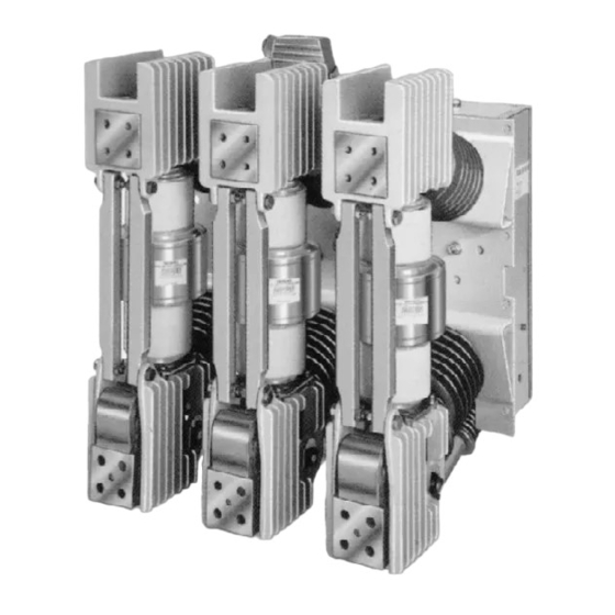
Siemens 3AH 사용 설명서 - 페이지 35
{카테고리_이름} Siemens 3AH에 대한 사용 설명서을 온라인으로 검색하거나 PDF를 다운로드하세요. Siemens 3AH 38 페이지. Vacuum circuit breaker operator module
Siemens 3AH에 대해서도 마찬가지입니다: 지침, 설치, 작동, 유지보수 (33 페이지), 설치 운영 및 유지보수 (20 페이지)

Appendix
Table A-1 a
Type 3AH Circuit Breaker Ratings (Historic "Constant MVA" Rating Basis)
These ratings are in accordance with the following standards:
ANSI C37.04-1979
Standard Rating Structure for AC High-Voltage Circuit Breakers Rated on a Symmetrical Current Basis
ANSI C37.06-1987
AC High-Voltage Circuit Breakers Rated on a Symmetrical Current Basis- Preferred Ratings and Related Required Capabilities
ANSI C37.09-1979
Standard Test Procedure for AC High-Voltage Circuit Breakers Rated on a Symmetrical Current Basis
ANSI C37.010-1979
Application Guide for AC High-Voltage Circuit Breakers Rated on a Symmetrical Current Basis
Measured Parameter
Nominal Voltage Class
General
Nominal 3-Phase MVA Class
Maximum Design Voltage ( V )
Rated
Voltage
Voltage Range Factor ( K ) "'
Insulation
Withstan d
Levels
Voltage Levels
Rated
Values
Continuous "'
Short-Circuit (at rated maximumdesign
Rated
Current
voltage) (
I nterrupting Time
Permissible Tripping Delay
Rated Maximum Design Voltage (V)divided
by K ( � V/K )
Current
Max. Sym I nterrupting ( K x I )
Related
Required
Short-Ti me Current ( K x I ) (3 seconds)
Capabili-
ties
Asymmetrical ( 1.6 x K x I ) '"
Closing
and
Latching
Peak ( 2.7 x K x I ) "'
(Momentary)
Footnotes
1. High close and latch ( m o mentary) rating available for special application
2. Maxi m u m voltage for which the circuit breaker is designed, and the upper l i m it for operation.
3. K is the ratio of the rated maxi m u m design voltage to the lower limit of the range of operating voltage in which the required symmetrical
and asym metrical interrupting ca pabilities vary in inverse proportion to the operating voltage.
4.To obtain the required symmetrical interrupting capability of a circuit breaker at an operating voltage between 1 /K times rated
maxi m u m design voltage and rated maxi m u m design voltage, the following formula shall be used: Required Sym metrical Interrupting
Ca pability = Rated S hort-Circuit Cu rrent ( I ) X [ ( Rated Maxi m u m Design Voltage ) I ( Operating Voltage ) 1
For operating voltages be low 1/K times rated maxim u m design voltage, the req u i red symmetrical interrupting capability of the circ u it
breaker shall be equal to K times rated short-circuit cu rrent.
5. Within the l i m itations stated in ANSI C37.04-1979, a l l values a pply to polyphase and l i ne-to-line fau lts. For single phase-to-g round fa u lts,
the specific conditions stated in clause 5.10.2.3 of ANSI C37.04-1979 a pply.
6. Current values in this row are not to be exceeded even for operating voltage below 1 /K times rated maxim u m design voltage. For ope rat-
ing voltages between rated maxi m u m design voltage and 1/K times rated maxi m u m design voltage, follow footnote 5 above.
7. Cu rrent values i n this row are independent of operating voltage up to and including rated maxi m u m design voltage.
8. " Nominal 3-Phase MVA Class" is included for reference only - this information is not l isted in ANSI C37.06-1987.
9. Standard d uty cycle is CO - 1 5sec - CO
Units
kV
MVA
••
'
kV rms
"
- -
Power Frequency
kV rms
Lightning Impulse (BIL)
kV crest
A rms
kA rms-
I ) "
sym
'
101
"I
Cycles
( Y )
Sec
KV rms
kA rms-
'
"
kA rms
kA rms
kA peak
Circuit Breaker T ype
5-3AH
5-3AH-
7-3AH-
1 5-3AH-
250
350
500
500
4.16
4.16
7.2
1 3.8
250
350
500
500
4.76
4.76
8.25
1 5.0
1.24
1.19
1.25
1.30
19
19
36
36
60
60
95
95
1 200
1 200
1 200
1 200
2000
2000
2000
2000
3000
3000
29
41
33
1 8
5
5
5
2
2
2
3.85
4.0
6.6
11.5
36
49
41
23
36
49
41
23
58
66
37
78
78 opt"'
77 opt"'
58 opt"'
97
111
62
132
1 32 opt m
97 opt"'
1 30 opt"'
1 5-3AH-
1 5-3AH-
38-3AH-
750
1000
1 500
13.8
1 3.8
38
750
1000
1 500
1 5.0
1 5.0
38
1.30
1.30
1.65
36
36
80
95
95
1 50
1 200
1 200
1 200
2000
2000
2000
3000
3000
3000
28
37
2 1
5
5
5
5
2
2
2
2
11.5
11.5
23
36
48
35
36
48
35
58
77
56
77 opt"'
97
1 30
95
130 opt"'
35
