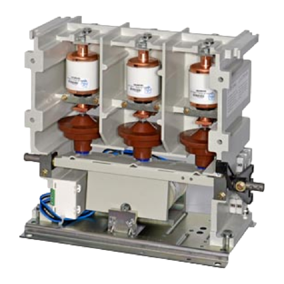
Siemens 3TL81 사용 설명서 - 페이지 4
{카테고리_이름} Siemens 3TL81에 대한 사용 설명서을 온라인으로 검색하거나 PDF를 다운로드하세요. Siemens 3TL81 20 페이지. High-voltage vacuum contactors

Technische Daten
Ausführung nach VDE 0660 Teil 103-1984
nach IEC-Publikation 470-1974
Typ
Bemessungsbetriebsspannung U e
Nennfrequenz
Bemessungsbetriebsstrom
nach Gebrauchskategorie
AC1, AC2, AC3 und AC4
bei Umgebungstemperatur bis + 55 °C
Max. zulässiger Kurzschlußwechselstrom
(Kurzschlußschutz siehe Seite 9/10)
max. Ausschaltzeit 120 ms
Max. zulässiger Stoßkurzschlußstrom
Max. Durchlaßstrom I D
bei HH-Sicherungen
Nennkurzzeitstrom 1s (Effektivwert)
Kondensatorkreis
Bemessungsbetriebsstrom
Zulässige Schalthäufigkeit
Wechselstrom-/Gleichstrombetätigung
(Schaltsp./h)
Mechanische Lebensdauer des Schützes
Mechanische Lebensdauer der Vakuum-
Schaltröhre
Elektrische Lebensdauer der Vakuum-
Schaltröhre
beim Abschalten des Nennstroms
Lebensdauer bei Lagerung
Zulässige Umgebungstemperatur
Lagerung bei -40 bis +65 °C Zeit
Betrieb des Vakuumschützes
bei -5 bis +65 °C Schaltspiele
bei -5 bis -25 °C Schaltspiele
Nennaufnahme des Steuerstromkreises
Wechselstrom-/Gleichstrombetätigung
Einschaltleistung
Halteleistung
Arbeitsbereich des Antriebsmagneten
Wechselstrom-/Gleichstrombetätigung
Mindesteinschaltbefehl für Antriebsmagneten
Ausschaltzeiten
in Abhängigkeit von der Sparschaltung
110 - 250 V
24 - 60 V
Mechanische Einschaltverklinkung
Zulässige Schalthäufigkeit
(Schaltsp./h)
AC/DC 110 - 380 V
DC 24 - 60 V
Schaltpause (min)
AC/DC 110 - 380 V
DC 24 - 60 V
2
Leitungsquerschnitt (mm
)
DC 24 - 60 V
Max. Leitungslänge [m]
DC 24 - 60 V
Lebensdauer der mechan. Einschaltverklinkung
(Schaltspiele)
Nennaufnahme des Entklinkungsmagneten
Wechsel- und Gleichstrombetätigung
1) Mechanische Einschaltverklinkung
4
Technical data
Designed to VDE 0660, part 103-1984
Contactor type
Rated voltage U e
Rated frequency
I
Rated operating current I e
e
according to utilization category
AC1, AC2, AC3 and AC4
at ambient temperature up to +55 °C
+ 65 °C
Initial symmetrical short-circuit current
(see page 9/10 for short-circuit protection)
opening time max. 120 ms
Peak short-circuit current
Maximum cut-off current I D
with HV-HRC fuses
Rated short-time withstand current,
1s (rms value)
Capacitor Circuits
Rated operating current
Permissible switching frequency
AC/DC operation
(operating cycles per hour)
Mechanical service life of the contactor
Mechanical service life of the vacuum
interrupter
Electrical service life of the vacuum
interrupter
when switching the rated operating current
Endurance in storage
Permissible ambient temperature
when stored with - 40 bis +65 °C
during operation of vacuum contactor
Rated input of the control circuit
AC/DC operation
when closing
when holding
Working range of the solenoid
AC/DC operation
Minimum closing command for operating solenoid
Opening times
at a function of the economy circuit
Mechanical closing latching
Permissible switching frequency
(operating cycles per hour) AC/DC 110 - 380 V
Time interval between operation cycles (min)
Cross section of leads (mm
Max. length of leads [m]
Service life of the mechanical closing latching
(operating cycles)
Rated input of unlatching solenoid
AC and DC operation
1) Mechanical closing latching
to IEC Publication 470-1974
+65 °C
period
with -5 bis +65 °C operating cycles
with -5 bis -25 °C operating cycles
110 - 250 V
24 - 60 V
DC 24 - 60 V
AC/DC 110 - 380 V
DC 24 - 60 V
2
)
DC 24 - 60 V
DC 24 - 60 V
3TL81
7,2 kV
50-60 Hz
400 A
360 A
20 kA
40 kA
50 kA
8 kA
250 A
1200
1 x 10
6
0,25 x 10
0,25 x 10
20 Jahre / years
20 Jahre / years
1 x 10
6
0,5 x 10
600 W
90 W
0,85 bis / to 1,1 U
U
= 24 / 48 - 60 / 110 - 250 V
s
300 bzw./resp. 500 ms
< 50 ms
325 ± 75 ms
200 ± 60 ms
(siehe Fig. 10 - 13 / see Figs. 10 - 13)
60
6
1
10
6
3
100 000
900 W
3ZX1812-TL80-0AN6 / 9229 9870 174 0G
6
6
6
C
1)
2003-03-12
