Siemens SIMATIC NET SINAUT MD720-3 시스템 매뉴얼 - 페이지 20
{카테고리_이름} Siemens SIMATIC NET SINAUT MD720-3에 대한 시스템 매뉴얼을 온라인으로 검색하거나 PDF를 다운로드하세요. Siemens SIMATIC NET SINAUT MD720-3 20 페이지.
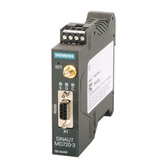
Connecting the device and switching on the device
Connectors for current supply
The screw terminals on the top of the device are for connecting the current supply:
24 V DC voltage (nominal), I
Technical Data.)
Both screw terminals on the left (24V) are internally connected, see figure 3-1.
Both screw terminals on the right (0V) are internally connected.
Switching on
The devices switch on as soon as the operating voltage is supplied.
Functions of the LEDs
The SINAUT MD720-3 has three LEDs, which are used to indicate the device
status. The function of the LEDs is different in terminal and OPC Mode. You will
find the explanation of the function
● in Terminal Mode in chapter 4.3 Functions of the LEDs in Terminal Mode and
● in OPC Mode in chapter 5.3 Functions of the LEDs in OPC Mode.
Serial interface X1
For data transmission:
Connect the application (e.g. machine, vending machine, sensor, computer) with
the interface X1 of the SINAUT MD720-3. To connect, use a RS-232 cable.
If the application has a different interface, e.g. CAN, PPI cable or a different
industry bus, a commercially available interface converter can be connected
between it and the SINAUT MD720-3.
OR
For configuration and service:
Connect the service PC via its serial interface (COM port). To connect, use a RS-
232 cable.
20
165mA at 24V. (Please also refer to chapter 7
typ.
SINAUT MD720-3
C79000-G8976-C211