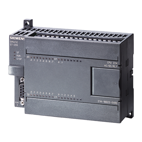
Siemens SIMATIC S7-200 매뉴얼 - 페이지 35
{카테고리_이름} Siemens SIMATIC S7-200에 대한 매뉴얼을 온라인으로 검색하거나 PDF를 다운로드하세요. Siemens SIMATIC S7-200 49 페이지. Ethernet gateway for simatic mpi/ profibus driver
Siemens SIMATIC S7-200에 대해서도 마찬가지입니다: 매뉴얼 (30 페이지), 매뉴얼 (35 페이지), 드라이버 매뉴얼 (28 페이지), 매뉴얼 (18 페이지), 시스템 매뉴얼 (20 페이지)

5.2
Second modification to the program
5.2.1
OR logic operation
Objective:
Switches S0 and S2 are to be actuated in
order to switch on the motor. Switch S3
alone is to be used as an alternative in order
to switch on the motor. Switch S1 is to be
used to reverse the direction of rotation of
the motor.
A description of the function shown above:
When (S0 AND S2) OR S3 are actuated, the motor runs. In the ladder diagram that means:
when contacts I0.0 AND I0.2 or I0.3 are closed, current flows from the power rail to coil
Q0.0. This is a parallel connection from S0 and S2 to S3 (OR logic operation). In our
program, the logic is expressed as follows:
We do not need to wire switch S3, since it is
already connected to input I0.3 via the
simulator. The next page describes how to
select and insert an OR logic gate with a
connecting line.
Getting Started - Beginners
Training Documents, 07/2007, A5E01031470B
5.2 Second modification to the program
Circuit without PLC
Ladder diagram of the circuit
More exercises
35
