Siemens SINAMICS G130 사용 설명서 - 페이지 18

{카테고리_이름} Siemens SINAMICS G130에 대한 사용 설명서을 온라인으로 검색하거나 PDF를 다운로드하세요. Siemens SINAMICS G130 26 페이지. Line filter
Siemens SINAMICS G130에 대해서도 마찬가지입니다: 사용 설명서 (24 페이지), 사용 설명서 (46 페이지), 사용 설명서 (24 페이지), 사용 설명서 (31 페이지), 사용 설명서 (30 페이지), 사용 설명서 (28 페이지), 사용 설명서 (30 페이지), 사용 설명서 (22 페이지), 사용 설명서 (28 페이지), 사용 설명서 (30 페이지), 사용 설명서 (34 페이지), 사용 설명서 (46 페이지), 사용 설명서 (26 페이지), 사용 설명서 (26 페이지), 사용 설명서 (28 페이지), 사용 설명서 (42 페이지), 사용 설명서 (46 페이지), 사용 설명서 (24 페이지), 사용 설명서 (24 페이지), 사용 설명서 (30 페이지), 사용 설명서 (42 페이지), 사용 설명서 (38 페이지), 사용 설명서 (46 페이지), 사용 설명서 (28 페이지), 사용 설명서 (22 페이지), 사용 설명서 (24 페이지)
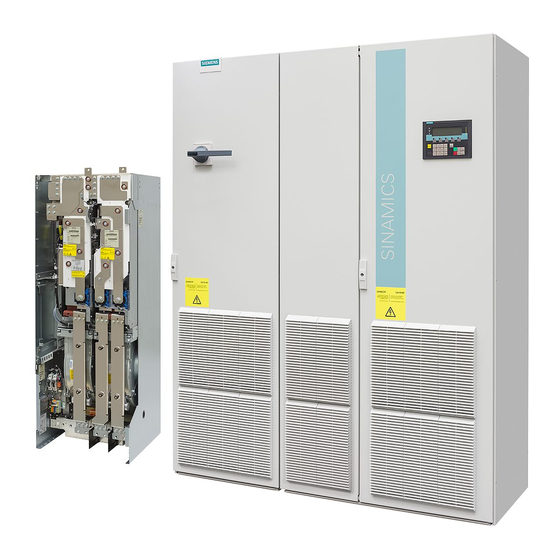
Siemens SINAMICS G130 사용 설명서
Electrical installation
4.2 Interface description
Table 4- 4
Terminal
X531
X532
X533
X534
X535
X536
NOTICE
Cable cross section
Cable length and cross section might influence the temperature measurement
(10 Ω cable resistance for a PT100, can falsify the measurement result by 10 %).
For cable lengths > 100 m, cables with a cross-section of ≥ 1 mm
NOTICE
The maximum cable length is 300 m and the cables must be shielded.
4.2.4

Meaning of the LEDs on the Terminal Module TM150

Table 4- 5
Meaning of the LEDs on the Terminal Module TM150
LED
Color
RDY
-
Green
Orange
Red
Green/
Red
Green/
orange
or
red/
orange
16
Channel assignment
Channel number [x]
for 1x2, 3 and 4-wires
0
1
2
3
4
5
State
Description
OFF
The electronic power supply is missing or lies outside the
permissible tolerance range.
Continuous light
The component is ready for operation and cyclic DRIVE-CLiQ
communication is taking place.
Continuous light
DRIVE-CLiQ communication is being established.
Continuous light
At least one fault is present in this component. Note:
The LED is activated regardless of whether the corresponding
messages have been reconfigured.
Flashing light
Firmware is being downloaded.
0.5 Hz
Flashing light
Firmware has been downloaded.
2 Hz
Wait for POWER ON.
Flashing light
Detection of the components via LED is activated (p0154).
2 Hz
Note:
Both options depend on the LED status when module recognition
is activated via p0154 = 1.
Channel number [y]
for 2x2 wires
6
7
8
9
10
11
must be used.
2
Terminal Module 150 (TM150)
Operating Instructions, 03/2012, A5E03758735A