Siemens SINAMICS G130 사용 설명서 - 페이지 13

{카테고리_이름} Siemens SINAMICS G130에 대한 사용 설명서을 온라인으로 검색하거나 PDF를 다운로드하세요. Siemens SINAMICS G130 42 페이지. Line filter
Siemens SINAMICS G130에 대해서도 마찬가지입니다: 사용 설명서 (24 페이지), 사용 설명서 (26 페이지), 사용 설명서 (46 페이지), 사용 설명서 (24 페이지), 사용 설명서 (31 페이지), 사용 설명서 (30 페이지), 사용 설명서 (28 페이지), 사용 설명서 (30 페이지), 사용 설명서 (22 페이지), 사용 설명서 (28 페이지), 사용 설명서 (30 페이지), 사용 설명서 (34 페이지), 사용 설명서 (46 페이지), 사용 설명서 (26 페이지), 사용 설명서 (26 페이지), 사용 설명서 (28 페이지), 사용 설명서 (42 페이지), 사용 설명서 (46 페이지), 사용 설명서 (24 페이지), 사용 설명서 (24 페이지), 사용 설명서 (30 페이지), 사용 설명서 (38 페이지), 사용 설명서 (46 페이지), 사용 설명서 (28 페이지), 사용 설명서 (22 페이지), 사용 설명서 (24 페이지)
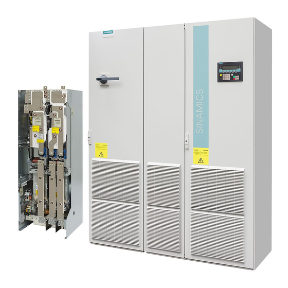
Siemens SINAMICS G130 사용 설명서
CAUTION
The 100 mm clearances above and below the components must be observed.
The dV/dt filters compact plus Voltage Peak Limiter may only be mounted in a vertical
position, to enable cooling air to flow through the heat sink on the Voltage Peak Limiter
from the bottom to the top.
Note
The motor cables between the Power Module and the dV/dt filter compact, as well as the
cables to the DC link, must be kept as short as possible (max. 5 m).
Note
The dV/dt filters compact plus Voltage Peak Limiter of Types 1 to 3 consist of one single
component. Type 4 consists of two separate components, the dV/dt reactor and the Voltage
Peak Limiter.
CAUTION
Terminals for order numbers 6SL3000-2DE41-4EA0, 6SL3000-2DG38-1EA0 and 6SL3000-
2DG41-3EA0
The terminals on the voltage limiting network (Voltage Peak Limiter) must always be
connected as follows:
 Cable from the DC link of the Power Module at DCPS, DCNS and
 Cable to the dv/dt reactor 1U2, 1V2, 1W2.
Failure to connect the terminals correctly could damage the voltage peak limiter.
CAUTION
If dV/dt filters compact plus Voltage Peak Limiters are used that SIEMENS has not
approved for SINAMICS, these dV/dt filters may be damaged.
The surface temperature of the dV/dt filters may exceed 80 °C.
When a dV/dt filter compact plus Voltage Peak Limiter is used with SINAMICS G130, the
pulse frequency of the Power Module must not exceed 2.5 kHz/4 kHz. Setting a higher
pulse frequency can lead to destruction of the dV/dt filter.
Note
Current derating at an increased pulse frequency depends on the derating of the associated
Power Module.
dV/dt filter compact plus Voltage Peak Limiter
Operating Instructions, 03/2011, A5E02590131A
CAUTION
WARNING
General
11