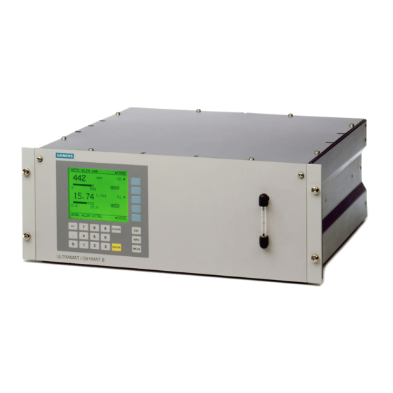
Siemens ULTRAMAT 6F 추가 장비 매뉴얼 - 페이지 11
{카테고리_이름} Siemens ULTRAMAT 6F에 대한 추가 장비 매뉴얼을 온라인으로 검색하거나 PDF를 다운로드하세요. Siemens ULTRAMAT 6F 20 페이지. Gas analyzer for the determination of ir-absorbing gases
Siemens ULTRAMAT 6F에 대해서도 마찬가지입니다: 사용 설명서 (49 페이지), 안전 매뉴얼 (24 페이지)

English
3.
Assembly
3.1
Connection of sample gas and protective gas (purging gas)
Installation should take place at a vibration-free location where possible and protected from direct
solar radiation. The analyzer and the EEx p safety device must be fixed according to their dimensional
drawings and connected according to the assembly diagram in Section 3.2 or 3.3. You can find the
dimensional drawings in the appropriate manuals. The following conditions must be observed for
trouble-free operation:
- When tightening union nuts on the gas couplings, use a suitable open-ended spanner to achieve
correct counterlocking; otherwise the danger exist that the gas path will leak.
- The operator must ensure the minimum pressure of the protective gases at the installation site. A
pressure of 0.2...0.4 MPa (2...4 bar) must be applied at the pressure regulator of the EEx p safety
device.
- When the protective gas is tapped, the pressure drop over the line should not amount to more than 5
hPa (5 mbar) at a flow of 50 /min. To achieve this, the exhaust air line must be dimensioned
accordingly (the length of the exhaust air line may be about 20 m at an internal diameter of G 1").
- The pre-purging time adjustable on the EEx p safety device (5 min with a purging gas flow of
50 l/min) must not be adjusted, i.e. dropped below!
- The EEx safety device is delivered with fixed basic parameters. The purging gas pressure is preset
to 105 hPa (rel.). Useful modifications such as reduction of the max. purging gas pressure can only
be made after studying the appropriate sections of the manual enclosed with the EEx p safety
device.
- Sample gas must not be supplied to the analyzer until the pre-purging phase has ended.
- It must always be guaranteed that the microflow sensor is surrounded by reference gas before the O
6F is switched on. Therefore the reference gas must also be connected (pre-purging period = 5 min)
when the EEx p safety device is switched on. The reference gas pressure must always be
0.2...0.4 MPa (2...4 bar) above the sample gas pressure.
- A key switch can be connected to the EEx p safety device (see Section 5.3 for details).
- Only for analyzer versions with "Compensation of losses resulting from leaks":
When using combustible sample gases, the difference between the purging gas and sample gas
pressures must be held constantly and reliably at more than 50 hPa. Differential pressure monitoring
must be provided for fail-safety. This should ensure that the EEx p safety device switches off the
analyzer and goes into the pre-purging phase when a set pressure difference is fallen below. It is up
to the user to select a suitable differential pressure monitoring device (e.g. differential pressure
switch).
The sample gas inlet of the O 6F contains a choke which creates a dynamic pressure to damp
pulsating flows. It is therefore recommendable to remove this choke if the differential pressure is to
be monitored (in versions "Compensation of losses resulting from leaks"). The damping measure
(choke) should be fitted upstream of the pressure measuring point when required.
- Only for analyzer versions with "Continuous purging":
Depending on the density of the sample gas, the inlet on the housing for the protective gas must be
selected as follows:
Sample gas density > protective gas density:
Sample gas density < protective gas density:
E-8
Inlet: coupling 6;
outlet: coupling 7
Inlet: coupling 5;
outlet: coupling 8
Additional Equipment Manual EEx p
Order No.:
A5E 000
58873-02
