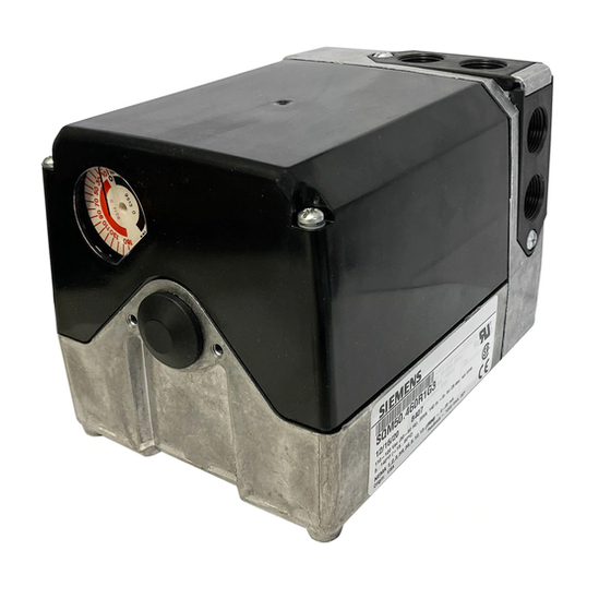
Siemens SQM56.667R1A3R 기술 지침 - 페이지 16
{카테고리_이름} Siemens SQM56.667R1A3R에 대한 기술 지침을 온라인으로 검색하거나 PDF를 다운로드하세요. Siemens SQM56.667R1A3R 31 페이지. Reversing
Siemens SQM56.667R1A3R에 대해서도 마찬가지입니다: 기술 지침 (31 페이지), 기술 지침 (31 페이지)

Technical Instructions
Document No. 155-517P25
July 9, 2007
Cover Installation
Features of
SQM5x.xxxxxZx
Actuators
Multiple Input Signals
Multiple Output Signals
Page 16
1.
Lift the two screws on the cover corners and slide the cover end into the grooves
at the gear end of the actuator. See Figure 14.
2.
Press the cover into place and then press the screws inward and tighten. See
Figure 15.
Figure 14.
SQM5xx.xxxxxZx actuators contain the AGA56.9A... multi function circuit board. This
circuit board provides the following features:
The AGA56.9A... circuit board accepts the following input signals:
Line voltage
•
Power to A drives the actuator open to the setting of switch cam I (Maximum).
•
Power to ZL drives the actuator closed to the setting of switch cam III (Minimum).
•
Power to Z drives the actuator closed to the setting of switch cam II (Economy).
•
4 to 20 mA (Signal to Y3, common to M)
•
0 to 135 Ω (Slide wire signal to Y0, potentiometer connected to M and U4)
•
0 to 10 Vdc (Signal to Y1, common to M)
•
0 to 20 mA (Signal to Y2, common to M)
The AGA56.9A... circuit board provides the following output signals:
•
4 to 20 mA (Signal from U3, common to M)
•
0 to 10Vdc (Signal from U1, common to M)
•
0 to 20mA (Signal from U2, common to M)
Double potentiometers ASZ22... provide additional output signals.
SQM5... Reversing Actuators
Figure 15.
Siemens Building Technologies, Inc.
