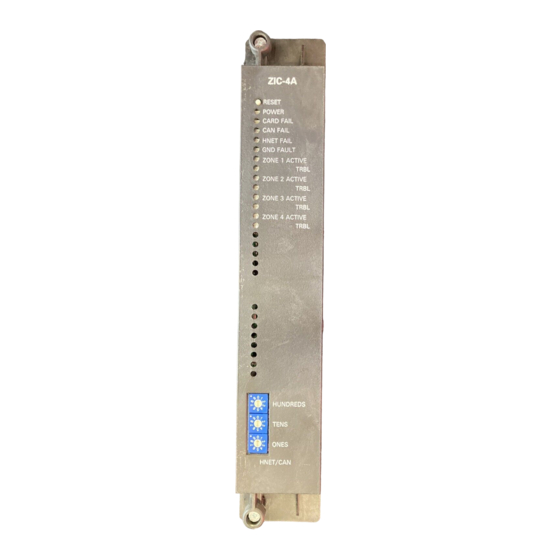
Siemens ZIC-4A 설치 지침 매뉴얼 - 페이지 9
{카테고리_이름} Siemens ZIC-4A에 대한 설치 지침 매뉴얼을 온라인으로 검색하거나 PDF를 다운로드하세요. Siemens ZIC-4A 24 페이지. Zone indicating card

Figure 4
Using Multiple Power Supplies
Siemens Industry, Inc.
Building Technologies Division
Care must be taken when installing the zone input and zone output field wiring to
prevent possible cross wiring. This can cause severe damage to the system
when powered up or when zone is activated.
The screw terminals can accommodate one 12-18 AWG or two 16-18 AWG.
If the total output of all 4 zones exceeds 12 amps, a single PSC-12 cannot be used to
supply the ZIC-4A. Refer to the PSC-12 Installation Instructions, P/N 315-033060 for
information when the total system load exceeds 12 amps.
17
18
TO PSC-12, TB4 +
TO PSC-12, TB4 -
17
18
TO PSC-12, TB4 +
TO PSC-12, TB4 -
TO PSX-12, TB4 +
TO PSX-12, TB4 -
17
18
TO PSC-12, TB4 +
TO PSC-12, TB4 -
TO PSX-12, TB4 +
TO PSX-12, TB4 -
ONE SLOT OF CC-5
19
20
21
22
23
24
ONE SLOT OF CC-5
19
20
21
22
23
24
ONE SLOT OF CC-5
19
20
21
22
23
24
9
USING A SINGLE
PSC-12 TO
POWER A ZIC-4A
USING A PSC-12 TO
POWER INPUTS 1-3
AND A PSX-12 TO
POWER INPUT 4
USING A PSC-12 TO
POWER INPUTS 1-2
AND A PSX-12 TO
POWER INPUTS 3- 4
P/N 315-033050-15
