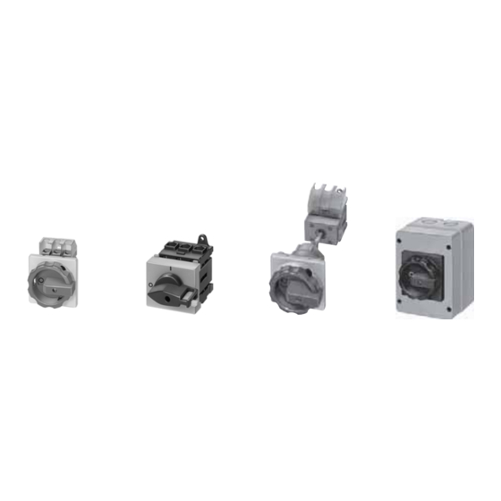
Siemens 3NP44 7 브로셔 - 페이지 12
{카테고리_이름} Siemens 3NP44 7에 대한 브로셔을 온라인으로 검색하거나 PDF를 다운로드하세요. Siemens 3NP44 7 50 페이지. Switch disconnectors and fuses

SENTRIC Switch Disconnectors
SENTRIC K Switch Disconnectors from 63 A to 1000 A
General data
■
Technical specifications
Standards
Type
Rated uninterrupted current I
Continuous thermal current I
Rated insulation voltage U
Rated impulse withstand voltage U
Rated operating voltage U
AC 50 Hz/60 Hz
DC
Rated short-circuit making capacity
4
with back-up fuses
)
at AC 50 Hz/60 Hz 690 V
Rated conditional short-circuit current with series-
4
connected fuses
)
at AC 50 Hz/60 Hz 690 V
Max. rated current I
of the fuses
n
Permissible let-through current of the fuses
Maximum permissible let-through I
Permissible let-through current of a series-con-
nected circuit-breaker
7
at AC 50 Hz/60 Hz 690 V
Rated short-circuit making capacity
without fuses
at AC 50 Hz/60 Hz 690 V
Switching capacity (infeed top or bottom)
at AC 400 V
Breaking current I
(p.f. = 0.35)
c
Rated operating current I
AC-21A, AC-22A, AC-23A
Motor switching capacity at AC-23A
At AC 500 V
Breaking current I
(p.f. = 0.35)
c
Rated operating current I
AC-21A, AC-22A
AC-23A
Motor switching capacity at AC-23A
at AC 690 V
Breaking current I
(p.f. = 0.35)
c
Rated operating current I
AC-21A, AC-22A
AC-23A
Motor switching capacity at AC-23A
at DC 440 V (3 conducting paths connected in series)
Breaking current I
(L/R = 15 ms)
c
Rated operating current I
Rated short-time current (1 s current)
Permissible load
depending on the ambient temperature for open-type
installation in switchboards (e.g. 8NA1) in switchgear
cubicles or switchgear racks at
35 °C
40 °C
45 °C
50 °C
55 °C
60 °C
Permissible ambient temperature
1) Technical specifications for CSA approval on request.
2) Configuring note: max. permissible operating temperature at connections
100 °C.
3) With 3KA58 for operation –25 °C ... +35 °C, 570 A at 55 °C.
4) Only for 3NA38, 3NA32 or 3ND18, 3ND12 fuses (105 kA/50 kA for others).
5) 3ND1 switchgear protection fuses.
6) AC-23B.
7) At 440 V L/R = 4 ms, at 220 V L/R = 15 ms.
8) At 440 V DC-22A, at 220 V DC-23A.
7/12
Siemens LV 10 · 2004
A
u
2)
A
th
V
i
kV
imp
e
V
V
kA (peak value)
kA (rms value)
A
kA
2
2
t value
kA
s
kA (peak value)
kA (peak value)
A (rms value)
at
e
A
kW
A (rms value)
at
e
A
A
kW
A (rms value)
at
e
A
A
kW
A
at DC-23A
A
e
kA (rms value)
A
A
A
A
A
A
°C
IEC 60947-1, IEC 60947-3, VDE 0660 Part 107
3KA50
3KA51
3KA52
63
80
125
63
80
125
690
690
1000
6
6
8
690
440 (3 conducting paths series-connected),
220 (2 conducting paths series-connected)
220
220
220
100
100
100
63
80
160
8
10
17
55
55
223
7
8
8
7
7
7
500
650
1000
63
80
125
30
40
65
500
640
1000
63
80
63
80
125
40
50
90
500
500
1000
63
80
125
63
63
125
50
50
110
250
260
500
63
63
125
2.5
2.5
3.2
63
80
125
63
80
125
63
80
125
63
80
125
63
80
125
63
80
125
–25 ... +55 for operation, –50 ... +80 for storage
1)
1)
3KA53
3KA55
3KA57
160
250
400
160
250
400
1000
1000
1000
8
8
8
220
220
220
100
80
80
160
400
400
5)
5)
17
30
30
223
1000
1000
15
25
25
9
20
25
1280
2000
3200
160
250
400
80
132
200
1280
2000
3200
160
250
400
160
250
400
110
185
280
1280
2000
3200
160
250
400
160
250
400
150
220
375
7)
640
1000
1600
8)
160
250
400
3.2
8
11
160
250
400
160
250
400
160
250
400
160
250
400
160
250
400
160
250
400
3)
3KA58
3)
630
3)
630
1000
8
220
50
630
5)
40
2600
32
35
5040
6)
630
350
3200
630
6)
400
280
3200
630
6)
400
375
1600
400
15
630
620
600
580
560
550
