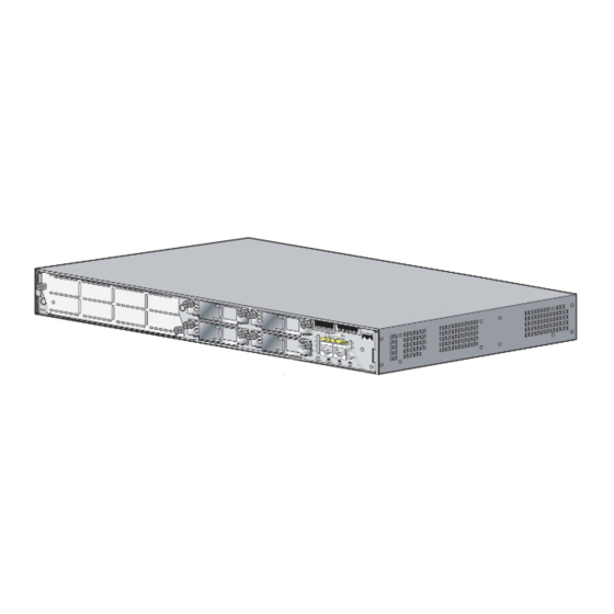
Cisco 2821 Series 설치 및 업그레이드 - 페이지 12
{카테고리_이름} Cisco 2821 Series에 대한 설치 및 업그레이드을 온라인으로 검색하거나 PDF를 다운로드하세요. Cisco 2821 Series 21 페이지. 2800 series integrated services routers
Cisco 2821 Series에 대해서도 마찬가지입니다: 데이터시트 (20 페이지), 운영 (31 페이지), 운영 (31 페이지), 빠른 시작 매뉴얼 (47 페이지)

Upgrading the Cisco 2821 and Cisco 2851 Fan Unit
Removing the Router Cover
To access the Cisco 2821 or Cisco 2851 fan unit, you must first remove the bezel and then remove the
router cover. The bezel is the front plastic panel on the chassis, which has the Cisco logo, LEDs, ports,
and input power connection.
To remove the bezel and router cover, complete the steps that follow. You will need a number 2 Phillips
screwdriver.
If your router uses AC or DC power, observe the following warning:
Warning
Do not touch the power supply when the power cord is connected. For systems with a power switch,
line voltages are present within the power supply even when the power switch is off and the power
cord is connected. For systems without a power switch, line voltages are present within the power
supply when the power cord is connected. Statement 4
If your router uses DC power, observe the following warning:
Before performing any of the following procedures, ensure that power is removed from the DC circuit.
Warning
Statement 1003
Step 1
Power down the router and disconnect the power cord from the front of the router.
Before opening the unit, disconnect the telephone-network cables to avoid contact with
Warning
telephone-network voltages. Statement 1041
Disconnect all network interface cables from the back panel of the router.
Step 2
Place the router on a flat surface.
Step 3
Remove the bezel from the front of the router. Follow these steps.
Step 4
Before removing the bezel, make sure that the flash memory card ejector button is flush with the bezel.
Caution
If the button projects from the bezel, removing the bezel can damage it.
Installing and Upgrading Fans in the Cisco 2821 and Cisco 2851 Series Routers
12
78-18643-02
