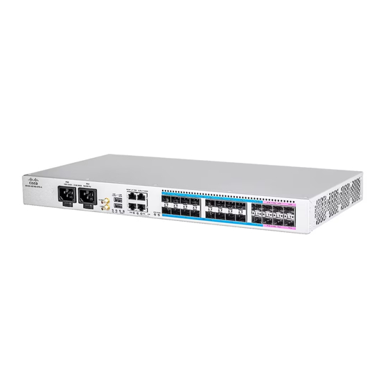
Cisco N540X-6Z18G-SYS-D 매뉴얼 - 페이지 19
{카테고리_이름} Cisco N540X-6Z18G-SYS-D에 대한 매뉴얼을 온라인으로 검색하거나 PDF를 다운로드하세요. Cisco N540X-6Z18G-SYS-D 30 페이지.
Cisco N540X-6Z18G-SYS-D에 대해서도 마찬가지입니다: 설치 준비 (14 페이지)

Install the Device
Figure 27: Attach the DC Power Supply Wires
Activate a DC Power Supply Module
Perform the following procedure to activate a DC power supply:
1. Verify the power supply operation by checking whether the respective power supply front panel LED
(PS0 or PS1) is green.
2. If the LEDs indicate any issues with power problem, see Troubleshooting.
3. If you are also connecting a redundant DC power supply, repeat these steps for the second power source.
Note
The operating voltage range is -20V to -72VDC.
Port Connection Guidelines
To prevent damage to the fiber-optic cables, we recommend that you keep the transceivers disconnected from
their fiber-optic cables when installing the transceiver in the line card. Before removing a transceiver from
the router, remove the cable from the transceiver.
To maximize the effectiveness and life of your transceivers and optical cables, do the following:
• Wear an ESD-preventative wrist strap that is connected to an earth ground whenever handling transceivers.
• Do not remove and insert a transceiver more often than is necessary. Repeated removals and insertions
If you are connecting a redundant DC power supply, ensure that each power supply is connected to a
separate power source in order to prevent power loss in the event of a power failure.
The router is typically grounded during installation and provides an ESD port to which you can connect
your wrist strap.
can shorten its useful life.
Activate a DC Power Supply Module
Install the Device
19
