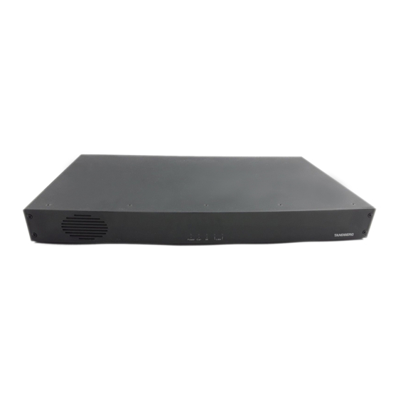
Cisco TelePresence System Codec 6000 MXP 물리적 인터페이스 매뉴얼 - 페이지 25
{카테고리_이름} Cisco TelePresence System Codec 6000 MXP에 대한 물리적 인터페이스 매뉴얼을 온라인으로 검색하거나 PDF를 다운로드하세요. Cisco TelePresence System Codec 6000 MXP 28 페이지.

MXP Series Codecs
Contents
Network Interface Sockets
TIP!
Wherever applicable, the use of Category
5 cabling or better is strongly recommended!
For HD camera applications, however,
Category 7.5 is required.
USB
interface.
For future
use.
Data port
Pin
Signal name
1
Carrier detect, CD
2
Receive data, RXD
3
Transmit data, TXD
4
Data terminal ready,
DTR
5
Signal GND
6
Data set ready, DSR
7
Ready to send, RTS
8
Clear to send, CTS
9
Ring indicator, RI
D14790.01 MXP Series Codec Physical Interface Guide, May 2011.
© 2011 Cisco Systems, Inc. All rights reserved.
Introduction
Wireless LAN PC card may
be inserted here.
The Data port is implemented
as a Digital Circuit Terminating
Equipment (DCE).
9-pin D-sub pin-out
Direction
External view of socket
From DCE
5
1
From DCE
To DCE
From DCE
9
6
From DCE
To DCE
From DCE
From DCE
Codec 6000 MXP
Ethernet LAN (RJ-45 Jack) interface
(10/100 Mb). Up to 4 or 6 Mbps, depending
on the bandwidth option installed. Use any
standard Ethernet cable to connect the Codec
to a LAN.
If no LAN is available and the Codec is
connected directly to a computer, use a
crossover cable.
Ethernet cable
Wiring diagram of
a standard cable
1
-------
1
2
-------
2
3
-------
3
6
-------
6
25
Physical interface guide
Codec 3000 MXP
Codec 3000 MXP
TIP!
If you connect your Codec directly to a PC, make
sure you set up the system to use static TCP/IP settings.
There will be no DHCP server controlling the little
LAN created by the computer and the Codec. When
configuring a back-to-back connection between the
PC and the Codec, make sure both static IP addresses
exist on the same subnet.
Ethernet cable
Wiring diagram of
a crossover cable
1
1
2
2
3
3
6
6
Contact us
RJ-45 Connector
pin-out
1
8
TOP
FRONT
1
8
www.cisco.com
