Sony SA-CT290 서비스 매뉴얼 - 페이지 5
{카테고리_이름} Sony SA-CT290에 대한 서비스 매뉴얼을 온라인으로 검색하거나 PDF를 다운로드하세요. Sony SA-CT290 42 페이지. Sound bar and active speaker system

ADVANCE PREPARATION WHEN CONFIRMING OP-
ERATION
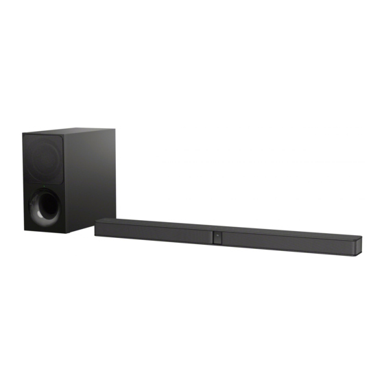
All the units included in the HT-CT290/CT291 (SA-CT290/
CT291, SA-WCT290/WCT291, remote control) are required to
confi rm the operation of SA-CT290/CT291. Check in advance that
you have all the units.
NOTE OF REPLACING THE IC1001 ON THE MAIN
BOARD AND THE COMPLETE MAIN BOARD
When IC1001 on the MAIN board and the complete MAIN board
are replaced, it is necessary to use termo sheet.
Spread the compound referring to the fi gure below.
– MAIN Board (Conductor Side) –
NOTE OF REPLACING FOOT (CG-BAR)
After remove the FOOT (CG-BAR), it is required to replace new
FOOT (CG-BAR).
NOTE OF ASSEMBLE THE CABINET ASSY
When assemble the CABINET ASSY, make sure the wire is away
from the inductor.
termo sheet
IC1001
NG
Wire near to inductor
inductor
OK
Wire away from inductor
inductor
– Rear view –
NOTE OF DISASSEMBLE PANEL, FRONT
When disassemble the PANEL, FRONT, tweezer is required to
remove cover and cover, screw. Remove through the service hole.
tweezer service holes
service hole
– Rear view –
NOTES ON THE WIRELESS CONNECTION (LINK) AFTER
REPAIRS ARE COMPLETE
When the parts below is replaced, the wireless connection (LINK)
of the Bar speaker and Subwoofer will be disconnected.
Before returning repaired products to the customer, follow the pro-
cedure below to LINK the Bar speaker and Subwoofer.
Also, if only the Bar speaker or Subwoofer is brought in for repair
and the parts below are replaced, be sure to inform the customer
when returning the repaired products that the customer must LINK
the Bar speaker and Subwoofer.
(Indicate that the LINK procedure is described in the operating
instructions)
Parts in which the LINK will be disconnected due to re-
placement:
•
Complete MAIN board
•
IC2000 on the MAIN board (Serial Flash)
•
Bluetooth Module (WB116A X) (Ver C)
HT-CT290/CT291
5
