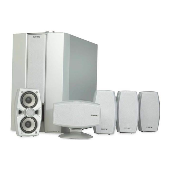
Sony SA-WMS535 서비스 매뉴얼 - 페이지 7
{카테고리_이름} Sony SA-WMS535에 대한 서비스 매뉴얼을 온라인으로 검색하거나 PDF를 다운로드하세요. Sony SA-WMS535 14 페이지. Micro satellite system
Sony SA-WMS535에 대해서도 마찬가지입니다: 서비스 매뉴얼 (14 페이지)

- 1. Table of Contents
- 1. 1 Diagrams
- 1. Circuit Boards Location (SA-WMS535)
- 1. Printed Wiring Boards (SA-WMS535)
- 1. Schematic Diagram (SA-WMS535)
- 2. 2 Exploded Views
- 2. Front Panel Section (SA-WMS535)
- 2. Rear Panel Section (SA-WMS535)
- 2. Front and Rear, Center Speaker (SS-MS535)
- 3. 3 Electrical Parts List
NOTE:
• The mechanical parts with no reference
number in the exploded views are not supplied.
• Items marked "*" are not stocked since
they are seldom required for routine service.
Some delay should be anticipated
when ordering these items.
• Abbreviation
AR : Argentina model
CND : Canadian model
MY : Malaysia model
SP
: Singapore model
2-1. FRONT PANEL SECTION
(SA-WMS535)
SP1
#1
#1
2
1
Ref. No.
Part No.
Description
1
X-4953-330-1 FRAME ASSY, GRILLE
2
X-4953-555-1 PANEL ASSY, FRONT (AEP,UK,SP,MY,AR)
2
X-4954-878-1 PANEL ASSY, FRONT (US,CND)
3
3-703-564-21 SCREW, TAPPING
4
4-227-298-01 SHEET
5
4-999-482-11 KNOB (VOL)
6
4-231-866-01 PACKING
SECTION 2
EXPLODED VIEWS
• Color Indication of Appearance Parts
Example :
KNOB, BALANCE (WHITE) ... (RED)
• Accessories are given in the last of this
parts list.
5
Supplied with
RV201 and S201
4
3
#2
3
Remark
SA-VE535H/WMS535/SS-MS535
R
R
Parts Color Cabinet's Color
6
8
7
9
#2
10
Ref. No.
Part No.
7
1-685-127-11 POWER SWITCH BOARD
8
4-973-938-31 KNOB (A), PUSH
9
1-685-128-11 LED BOARD
10
A-4729-384-A CONTROL BOARD, COMPLETE
SP1
1-825-151-11 SPEAKER (20cm)
#1
7-685-664-79 SCREW +P 4X20 TYPE1
#2
7-685-146-29 SCREW +P 3X8 TYPE2 SLIT
The components identified by
mark 0 or dotted line with mark
0 are critical for safety.
Replace only with part number
specified.
Les composants identifiés par une
marque 0 sont critiques pour
la sécurité.
Ne les remplacer que par une piéce
portant le numéro spécifié.
Description
Remark
7
