Digitrax DS74 매뉴얼 - 페이지 5
{카테고리_이름} Digitrax DS74에 대한 매뉴얼을 온라인으로 검색하거나 PDF를 다운로드하세요. Digitrax DS74 8 페이지. Complete train control

5.0 External hardware Input lines:
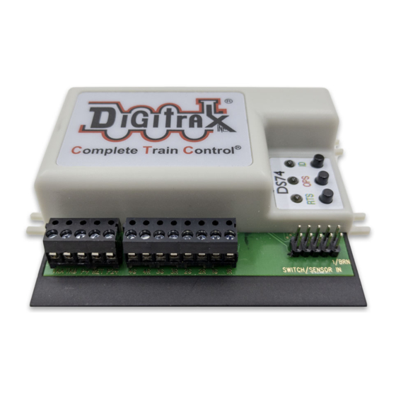
The DS74 has eight external hardware control lines on the "SWITCH/SENSOR
IN" pluggable 10 pin PCB header and the 10-pin ribbon cable. The 6" Factory
ribbon cable is color coded and the BROWN pin 1 side should be on the right side
when plugged in, as shown in Figure 1. If you use external lines, connect these
wires to your custom wiring by e.g. a screw terminal block. If using a non-color
code ribbon cable, make sure the pin numbers are correct for Table 2 usage.
A +5V Reference voltage is provided on pin 10/ribbon cable BLACK wire, and a
0V reference on pin 9 or the WHITE wire. DO not draw more than 100mA from
the BLACK wire. The SW/SENS wires pins 1/BROWN to 8/GRAY are rated for
up to +18V maximum input voltage.
1.
The lines SW1/BROWN, SW2/ORANGE,SW3/GREEN and SW4/VIOLET
wires will toggle the state of the same number output when briefly connected
to the +5V voltage on the BLACK wire or pin10. If the DS74 is connected to
LocoNet this will occur as a SW# message to make the change and notify the
system it has occurred. Use momentary press-ON buttons to control.
2.
The lines SENS1/RED, SENS2/YELLOW, SENS3/BLUE and SENS4/GRAY
will send a LocoNet Block Occupancy or DS message at the SW# of the
output. This will be BLOCK OCCUPIED when the line is above +4V and a
BLOCK UNOCCUPIED when between 0V/WHITE and +2V.
3.
For example; if the
SENS2/YELLOW line is
connected to the BLACK
+5V Reference wire, the
the DS number reported
will be SW# used for
Output 2R/2G. If SW10
is the BASE address of
the DS74, then Output2
is SW11 and the DS
message will be Block 11
OCCUPIED.
4.
A disconnected SENS
line will report as
UNOCCUPIED.
5.
The BD4N does not plug
directly into the 10 pin
header, and will not
operate. Connect the 5
wires used by the BD4N
by name via a terminal
strip. More conveniently, you may connect the BD4N through a DSXC4
connector with ribbon cables for true plug and play connectivity.
© 2021 Digitrax, Inc.
Table 2: DS74 Input lines
Pin# Wire Color
1
BROWN
2
RED
3
ORANGE
4
YELLOW
5
GREEN
6
BLUE
7
VIOLET
8
GRAY
9
WHITE
10
BLACK
— 5 —
Function
SW1 Toggle, +momentary
SENS1 occupancy level
SW2 Toggle, +momentary
SENS2 occupancy level
SW3 Toggle, +momentary
SENS3 occupancy level
SW4 Toggle, +momentary
SENS4 occupancy level
0V reference
+5V reference
www.digitrax.com
