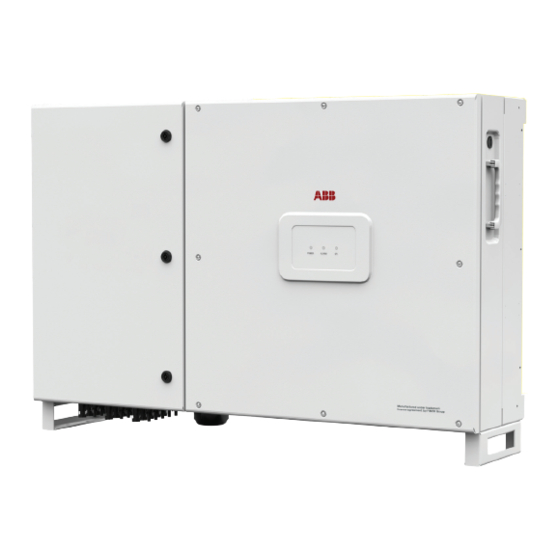
Fimer PVS-60-TL 빠른 설치 매뉴얼 - 페이지 7
{카테고리_이름} Fimer PVS-60-TL에 대한 빠른 설치 매뉴얼을 온라인으로 검색하거나 PDF를 다운로드하세요. Fimer PVS-60-TL 8 페이지. Solar inverter

As an alternative of QR code scanning, claiming process can be executed by selecting manually the SSIDs associated to the Wi-Fi networks generated
by each inverter to commission and inserting Product key when requested. Both QR code and Product key are provided on the Communication
identification label stuck onto each inverter. The Communication Identification label is divided in two separate parts by a dashed line; take the bottom
part and apply it on the plant documentation. (it's recommend to create a plant map and apply the Communication Identification label of each inverters
in the right position of that map).
Above steps are valid for executing any available funtionalities of the Installer for Solar Inverters mobile APP.
In order to launch the installation wizard and so complete the commissioning procedure please click "Commissioning" button.
If needed click prevently on "Firmware update" button for aligning the firmware of all the inverters in the list to the last version
(internet connection is needed).
READ THE MANUAL –
E
contact FIMER customer support. For any other specific settings of parameters of single inverters please refer to "Description of the Web User
Interface" chapter.
Commisioning via web UI (Access point wireless network)
The inverter can be commissioned and configured from a wireless device, such as a Smartphone, a tablet or a laptop. The commissioning procedure is
as follows:
1. Supply the input voltage from the photovoltaic generator to the inverter.
2. Enable the wireless functionality on the device you are using for the commissioning of the inverter the network named ABB-XX-XX-XX-XX-XX-XX,
where "X" is an hexadecimal number of the MAC Address (the MAC Address is indicated on the "wireless identification label" on the side of the inverter).
3. When prompted, type the "product key" (including the dashes. Example: 1234-1234-1234-1234) as the network password.
4. Open your Internet browser (recommended browsers: Chrome from v.55, Firefox from v.50, Safari from V.10.2.1) and enter the default IP Address to
access the Configuration Wizard page: 192.168.117.1.
5. This will start the Configuration Wizard:
- STEP 1 - Set the Admin/User access credentials (at least 8 characters for the password). Username and password are CASE SENSITIVE.
- STEP 2 (optional) - Enter the required information (IP Address selection mode, SSID, and password) to connect the inverter to the wire less network.
A new message will be displayed showing the IP Address assigned by router to access to the internal Web server. TAKE NOTE OF THE LINKS.
- STEP 3 - Set the Date, Time and Time Zone.
- STEP 4 - Set the inverter grid standard and configure the input channels. By clicking "FINISH" the wizard completes the configuration procedure (after
the settings are confirmed, the inverter restarts).
ATTENTION –
From the moment the grid standard is selected, there will be 24 hours available to make any changes to the grid standard; after this,
A
the "Country Select" feature is blocked and you can make further changes only by resetting the remaining-time timer.
6. Supply the grid voltage to the inverter.. Once the AC and DC disconnect switches are closed and the Configuration Wizard has completed the
configuration procedure, the inverter starts the grid connection sequence.
If the outcome of the preliminary checks is positive, the inverter will connect to the grid and start exporting power. The "Power" LED remains solid on,
while the "Alarm" and "GFI" LEDs are off.
READ THE MANUAL –
E
12. Features and Technical Data
Input
Absolute maximum input voltage (V
Input activation voltage (V
start
Operating DC input voltage range (V
Rated input DC voltage (V
)
dcr
Rated input DC power (P
)
dcr
Number of independent MPPTs
Maximum Input power for each MPPT (P
DC input voltage range (V
MPPT min
at P
acr
Maximum DC input current (Idc max) for each MPPT
Maximum input current short circuit current
(Idc max) for each MPPT
Maximum backfeed current (AC side vs DC side) Negligible in normal operating conditions
No. of DC input pairs for each MPPT
DC connection type
Type of PV panels connected in input in
accordance with Standard IEC 61730
Input protection
Reverse polarity protection
Input overvoltage protection for each MPPT-
SPD
Input overvoltage protection for each MPPT
- Surge Arrester
Isolation control
String fuses (models with fuses)
Output
AC connection to the grid
Rated AC output power (P
acr@cosφ=1
Maximum AC output power (P
Maximum apparent power (S
Rated AC grid voltage (V
)
acr
For more details about commissioning and any other functionalities of the Installer for Solar Inverters mobile APP please
For more information about the configuration and use of the internal Web server, refer to the product manual.
PVS-50-TL
)
1000 V
max,abs
)
420...700 V (default 420 V)
...V
)
0.7xVstart...950 V (min 300 V)
dcmin
dcmax
610 V
52000 W
3 (-SX and -SX2 versions) / 1 (standard version)
19300W@30°C/17500W@45°C
)
MPPTmax
... V
)
MPPT max
480...800 V
55A (165A for paralleled MPPTs)
5 (-SX and -SX2 versions)
Screw terminal block (standard model) / PV quick fit connector
Class A
Yes, from a limited current source
Yes, 1 for each MPPT
Type II / Type I+II (optional)
Complying with the local standard
15 A / 20 A | 1000 V / gPV
3W + GND (no N connection) or 4W + GND (with N connection)
Grounded WYE system only
)
50000 W
)
55000 W up to 30°C
ac max@cosφ=1
)
55000 VA up to 30°C
max
400 Vac
PVS-60-TL
420...700 V (default 500 V)
0.7xVstart...950 V (min 360 V)
720 V
61800 W
23100 W@30°C/21000 W@45°C
570...800 V
36 A
(3)
(-SX and -SX2 models)
(4)
60000 W
66000 W up to 30°C
66000 VA up to 30°C
480 Vac
7
