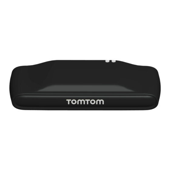
TomTom LINK 510 설치 매뉴얼 - 페이지 8
{카테고리_이름} TomTom LINK 510에 대한 설치 매뉴얼을 온라인으로 검색하거나 PDF를 다운로드하세요. TomTom LINK 510 16 페이지. Vehicle tracking device
TomTom LINK 510에 대해서도 마찬가지입니다: 설치 매뉴얼 (35 페이지), 사용자 설명서 (37 페이지)

Tracker Connect PTY LTD
NB: A Top side of the LINK 510 must not be obstructed by metal items.
B Keep minimum distance of 5 cm to metal items.
The electric supply circuitry can now be identified and obtained.
Must be a permanent 12V or 24V power source that never losses power at any
stage during the installation life of the TU.
Must be a charging power source that exceeds 13.1V in a12V-Vehicle and 26V in
a 24V-Vehicle.
The positive (Red) wire from the plug can now be connected to the obtained
power supply circuit.
NB: First connect the wires then insert the plug into the LINK 510. If you have
inserted the plug into the LINK 510 first, you must connect the GND wire before you
connect the PWR+ wire and the IGN wire.
NB: If you need to disconnect the wires while the 3-pin plug is plugged in the LINK
510 make sure you disconnect the GND wire last.
A suitable ignition source must be identified and obtained:
Ignition supply- must be an applied ignition circuit that must be a permanent and
an unregulated charging circuit. (Care must be taken not to mistake ignition for
accessory)
The ignition (Black) wire from the plug can now be connected to the obtained
ignition supply circuit.
A suitable earth point (negative source) must be identified obtained.
Must be a permanent and reliable negative source.
The negative (Brown) wire from the plug can now be connected to the obtained
negative earth stud.
The input wire (green/blue) must be connected to an earth stud if not used for
detecting other digital inputs
Issue: 1.1
Date: 17 October 2012
Author: Yolandie Viljoen
TomTom Installation
Guide
TSU-TTH-BTN-12-354-LINK 510 Installation Guide
TomTom LINK 510
Page: 8
