Crowcon TXgard-Plus 지침 - 페이지 2
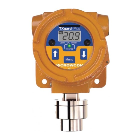
{카테고리_이름} Crowcon TXgard-Plus에 대한 지침을 온라인으로 검색하거나 PDF를 다운로드하세요. Crowcon TXgard-Plus 5 페이지. Flameproof toxic and oxygen gas detector
SK
SR
OUTPUT
4mA
40-200 mV
CONTACT
REVERSING
LINKS
GND
ISOLATE
LINK
ISOLATE
USED FOR
0V
GND
OXYGEN TXGARD.
FOR TOXIC LINK
OXYGEN
SET TO OTHER
OTHER
CONTROL
EQUIPMENT
TO
96HD
SENSOR
INTERNAL TERMINAL LAYOUT
= ALARM RELAY VERSION ONLY
Diagram 2: Terminal and amplifier layouts
2. DETECTOR CONFIGURATION
2.1 Standard configuration
As standard, TXgard-Plus is factory set as follows:
Current source with
0 mA
2 mA
4-20 mA
24 mA
AL1 relay (if fitted)
• Alarm level 1, see Table 3
• Normally de-energised, energising on alarm
• Contact normally open (NO), closing on
alarm
AL2 relay (if fitted)
• Alarm level 2, see Table 3
• Normally de-energised, energising on alarm
• Contact normally open (NO), opening on
alarm
FAULT relay (if fitted)
• Normally energised, de-energising on fault
• Contact normally closed (NC), opening on
fault
Alarm/fault relays automatically reset when alarm or fault has cleared.
INHIBIT
• Normally selected. ie. when CAL/ZERO
selected current output is forced to 2mA
and relays are held in normal/no alarm
state
Table 2: Standard configuration for TXgard-Plus.
REAR VIEW OF
AMPLIFIER
GAS
RANGE
ALARM
OUTPUT OPTIONS
TEST
INHIBIT
N Y
POINT
17 4 2
ALARM 1
ALARM 2
0V
10-30V
4-20mA
= Fault
= Inhibit ie. Zero/Cal mode
= Normal operation
= Over-range clamp
.
Table 3 details standard alarm points for the available gases and ranges.
Gas
Hydrogen sulphide
Carbon monoxide
Ammonia
Oxygen
Sulphur dioxide
* Alternative ranges and alarm set points must be specified when ordering
RELAY
CONTACTS
Table 3: Standard ranges and alarm set points.
ALARM2
Location of links are shown in Diagram 2.
ALARM1
2.2 4–20 mA options
FAULT
To change current source output to sink, set switch to 'SK' position.
ALARM
To change Inhibit from 2 mA to 4 mA, fit link to '4' position.
SET POTS
2.3 Relay options
To change AL1 or AL2 relay from NO to NC, fit link in the 'NC' position.
To change FAULT relay from NC to NO, fit link in the 'NO' position.
2.4 Inhibit options
To not inhibit 4-20 mA signal and relays, fit link to 'N' and link to '4'.
3. INSTALLATION
WARNING
TXgard-Plus is designed for use in Zone 1 and 2 hazardous areas and
is certified EEx d IIC T6 (AEx d IIC T6 in USA). Installation must be in
accordance with the recognised standards of the appropriate authority
in the country concerned. For more information contact Crowcon.
Prior to carrying out any work ensure local regulations and site
procedures are followed.
3.1 Location
There are no rules which dictate the siting and location of detectors, however,
considerable guidance is available from BS6959:1988 – 'British Standard
Code of Practice for the Selection, Installation, Use and Maintenance of
Apparatus for the Detection and Measurement of Combustible Gases'. In the
USA refer to the National Electrical Code (NEC 1999). Similar international
codes of practice may be used where applicable. In addition certain regulatory
bodies publish specifications giving minimum gas detection requirements for
specific applications.
The detector should be mounted where the gas is most likely to be
present. The following points should be noted when locating gas detectors:
• To detect gases which are lighter than air e.g. ammonia, detectors should
be mounted at high level and Crowcon recommend the use of a Collector
Cone, Part No. C01051.
• To detect heavier than air gases e.g. sulphur dioxide, detectors should be
mounted at low level.
• When locating detectors consider the possible damage caused by natural
events eg. rain or flooding. For detectors mounted outdoors Crowcon
recommend using a Weatherproof Cap, Part No. C01442.
• Consider ease of access for functional testing and servicing.
• Consider how the escaping gas may behave due to natural or forced air
currents. Mount detectors in ventilation ducts if appropriate.
• Consider the process conditions. Ammonia is normally lighter than air, but
if released from a process line which is cooled and/or under pressure the
gas may fall rather than rise.
2
Range*
AL1*
0–25 ppm
10 ppm
0–250 ppm
30 ppm
0–50 ppm
10 ppm
0–25% vv
19% vv
0–10 ppm
2 ppm
AL2*
20 ppm
100 ppm
25 ppm
17% vv
5 ppm