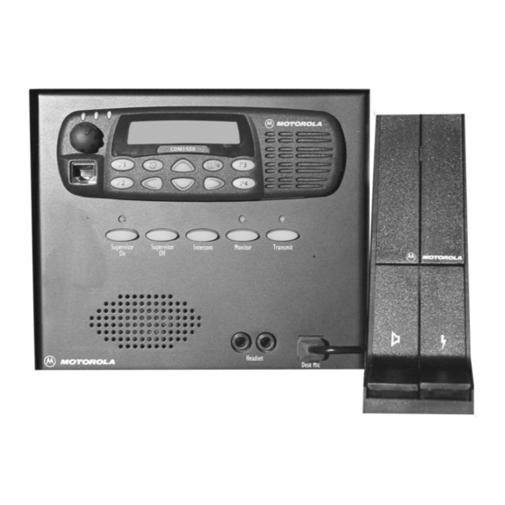
Motorola CDM Series 서비스 및 설치 매뉴얼 - 페이지 20
{카테고리_이름} Motorola CDM Series에 대한 서비스 및 설치 매뉴얼을 온라인으로 검색하거나 PDF를 다운로드하세요. Motorola CDM Series 32 페이지. Cdm-series control station

CDM Control Station Installation
Basic Disassembly/Assembly
Attaching the AC Power Cord
1.
Locate the AC power cord and a nylon tie wrap.
2.
Plug the female connector of the AC power cord
into the IEC receptacle located on the back of the
power supply.
Figure 3-2. Service Loop
3.
Use the tie wrap to anchor the "service loop" to the
chassis through the two holes in the bottom of
chassis as shown in Figure 3-2. Trim off the excess
tie wrap.
Replacing the Cover
1.
Rotate the cover and stand on its end such that the
rear panel (with fan) is on the surface with the inside
facing the rear of the enclosure base.
2.
Lower the cover onto the enclosure base by tilting
the top (as it stands) toward the front panel.
3.
Align the mounting holes and ensure all cables are
inside of the unit.
4.
Using a T15 Torx driver, secure the cover to the
base with the six (6) TT 3.5mm, pan head Taptite
screws removed in Step 3, "Removing the Housing
Cover".
Field Installation
To operate the Control Station, the AC line cord, antenna
feed line, ground cable, and optional accessory cable must
exit from the rear of the unit.
In addition, you must connect all of the necessary cables and
accessories as follows:
1.
Attach a ground wire from an absolute earth
ground to the 1/4" threaded ground stud on the left
of the station housing.
2.
Connect lightening arrestors.
3.
Connect the antenna lead to the antenna connector
on the back panel of the Control Station housing.
3-4
Tie
Wrap
6880309N15-A
IMPORTANT
Before connecting the AC line cord into an
AC mains outlet, ensure that the "115/230"
VAC switch on the power supply is in the
appropriate position. The switch is accessible
from the bottom of the Control Station hous-
ing.
4.
Plug the AC line cord into an AC mains outlet.
CDM Control Station
October, 2004
